Help with OLED and ESP32

Thread Starter

teenflon5

Joined Apr 19, 2021
27
Hello,

I'm doing my first project using an ESP32 and OLED display but think I might have jumped in at the deep end.

I'm using the OLED Display linked below;
https://www.aliexpress.com/item/1005003663739056.html?spm=a2g0o.order_list.0.0.17a718020DfdMB

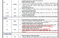
It has a driver built into it, which supports I2C, but from the pin diagram of the 30 pin connector below I dont quite know how to configure this with the ESP32.

  • Under Driver, pin 4, it says Voltage Output High Level for COM signal and to add a capacitor. What do I do with this?
  • Same for pin 27, Voltage Output Low Level for SEG signal. Do I ignore these?
  • In Interface, I'm not sure what I connect to the ESP32 and what else I might need to do with chip select etc?

Any help in trying to make sense of the pin out would be a great help!

Thanks
 

MrSalts

Joined Apr 2, 2020
2,767
Sorry, but the AliExpress description is not reality. This display can support parallel and SPI serial (as 3-wire or 4-wire versions).
From the datasheet on the aliexpress listing that you posted...
B69C0980-0704-4C14-9E3C-E9C32D371733.jpeg

You purchased a pretty common SD1322 OLED glass. You could have simplified life significantly (you still can) by buying one of these glasses on a PCB - like this...
https://www.aliexpress.com/item/325...316600454628793912ec93f!12000026691917156!rec

Or one made by Newhaven Displays if you want more and better documentation.
 

ericgibbs

Joined Jan 29, 2010
18,766
When and if we find out which OLED module type he has on his work bench, then our guesses should improve.
Perhaps a photo shot of the module type he is using will tell us more, maybe
 

Thread Starter

teenflon5

Joined Apr 19, 2021
27
@ericgibbs @MrSalts Ah yes thanks, I think the AliExpress description is garbage. I thought as it has a built in driver and they mentioned I2C it would work, but I suspect I need the other PCB part to make it I2C. Is there a fairly easy way to make the serial work with ESP32 or shall I just get another screen?
screen.jpg
 
Last edited by a moderator:

MrSalts

Joined Apr 2, 2020
2,767
The ESP-32 works just fine with SPI was well. I'm not sure the PCB alone will turn this glass into I2c. I haven't found one and have used these displays for several projects.
 

ericgibbs

Joined Jan 29, 2010
18,766
hi t5,
What type of data are you planning to display on the OLED is it just AlphaNumeric or do you intend to also use graphics.??
E

EDIT: Corrected type LCD > OLED
 
Last edited:

Ian0

Joined Aug 7, 2020
9,667
Pins 16 and 17 set the interface. You can have Intel or Motorola parallel, or 3 or 4-wire SPI.
3 wire is standard SPI. 4 wire SPI isn’t really SPI at all because it uses and extra line to indicate whether the interface is sending a command or data.
It doesn’t do I2C

capacitor between pin 4 and ground
leave pin 25 open circuit
 

Thread Starter

teenflon5

Joined Apr 19, 2021
27
Thanks all, I will do some reading up on SPI and how to do this with the display, certainly not an expert in this but will give it a go! It will be to display some graphics and text.
 

Ian0

Joined Aug 7, 2020
9,667
Thanks all, I will do some reading up on SPI and how to do this with the display, certainly not an expert in this but will give it a go! It will be to display some graphics and text.
I‘ve done it from scratch in ARM assembler, displaying a simple bargraph and text in three sizes.
It‘s a two stage process. First you define the limits of a rectangle that you want to write to, then you send data for each pixel in the rectangle.
The main problem (if it’s a pcb you have assembled yourself) is knowing whether you have a software problem or whether the ribbon connector is correctly in the socket and that there are no solder bridges.
 

Thread Starter

teenflon5

Joined Apr 19, 2021
27
I think I have bitten off more than I can chew. I found a datasheet for the driver which gives a lot more detail, but also a little overwhelming! There is a table for the pins and what each do, most I understand but some not quite sure. The most confusing part is in relation to the power supply pins and how they must be connected between capacitors. There is a diagram which explains this in 8.10 but capacitors are referred to again in other pins which arent mentioned in the diagrams. Might have a go at trying to make the circuit, but if I get any issues I doubt i'll be able to troubleshoot them!

Datasheet - https://newhavendisplay.com/content/app_notes/SSD1322.pdf
Section 7 is pin descriptions, 8.10 is the power circuit layout.
 

MrSalts

Joined Apr 2, 2020
2,767
I think I have bitten off more than I can chew. I found a datasheet for the driver which gives a lot more detail, but also a little overwhelming! There is a table for the pins and what each do, most I understand but some not quite sure. The most confusing part is in relation to the power supply pins and how they must be connected between capacitors. There is a diagram which explains this in 8.10 but capacitors are referred to again in other pins which arent mentioned in the diagrams. Might have a go at trying to make the circuit, but if I get any issues I doubt i'll be able to troubleshoot them!

Datasheet - https://newhavendisplay.com/content/app_notes/SSD1322.pdf
Section 7 is pin descriptions, 8.10 is the power circuit layout.
The sdd1322 is already in your glass. Newhaven resells the OLED glass but the also sell the PCB which connects all of the various pins on the glass's ribbon cable. Leaving only a few through-hole pins that you need to connect via SPI.
 

Thread Starter

teenflon5

Joined Apr 19, 2021
27
The sdd1322 is already in your glass. Newhaven resells the OLED glass but the also sell the PCB which connects all of the various pins on the glass's ribbon cable. Leaving only a few through-hole pins that you need to connect via SPI.
That is interesting I didn’t know that, that would be a lot simpler than my trying to use the ribbon cable! Will have a search
 
Top