Help with latching switch circuit?

Thread Starter

apqo1

Joined Oct 5, 2008
52
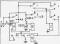
I'm working on a custom car and I need a switching circuit. I'm more mechanically minded than electical, so I've been unable to work it out myself. I'm hoping someone here would be willing to take a stab at it. Here's what I need:

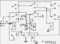
- Constant +12V input.
- Two switched +12V outputs, A & B.
- One momentary contact pushbutton switch.

First push/release of the switch latches output A to +12V (B remains zero V). Second push switches output B to +12V only as long as the switch is held closed (output A remains +12V). Third push/release unlatches output A; circuit returns to original state.

I would prefer to accomplish this with discrete components and relays if possible. I'm sure it could be done with a digital logic circuit, but that's way beyond my capabilities.

Many thanks!
 
Last edited:

Bernard

Joined Aug 7, 2008
5,784
Here is one version . Relays used are Potter & Brumfield R 10-E 1-W2,V700 24 V DC, 2P2T to select caps & desistor. Operation is : Push once[ <1 sec ],RY A latches giving continous +12 V at Output A. Second continous push closes RY B & latching RY C; output 12 V now at A & B. Releasing sw opens RY B allows third push toclose RY D releasing all latched relays except D . Releasing switch returns all to initial conditions.
Time delay , 1+ sec. ,on RY B allows a short pulse to close A and not close B , latching D prevents inavertant re triggering. Well at least it's mostly relays . Must be a bug or in there , who can find them _no prizes.
 

Attachments

Last edited:

Bernard

Joined Aug 7, 2008
5,784
Suggestion: Add a wire or small resistor from top of RY B coil to NO contact near top of RY D; to dump charge on 2200 μ F cap. Cap 220 not needed ?
 

Bernard

Joined Aug 7, 2008
5,784
' connected 4 miscelaneous relays, substitutrd a diode for 220 μF cap. & adjusted R & C values to fit relays & wala_it works. Note: no supression on coils, @ low power a little arc keeps the contacts clean.
 

Thread Starter

apqo1

Joined Oct 5, 2008
52
Great, thanks! A couple more questions...

If I used a 20kΩ pot and a 220μF cap, the delay would be adjustable from 0 to ~4.4 sec, right?

I'm learning schematic drawing at the same time... Could you take a look at this and see if it looks right? I added D2 to protect Q1 from RLY2's field collapse.

Thanks again for all your help!
 

Attachments

Last edited:

Bernard

Joined Aug 7, 2008
5,784
Looks great, wire as shown on your drawing + new addition. Base dischagre current measures 3 ma, so no problem. On breadboard max R was 19 k, min 680, so your pot has it well covered. My Q is 2N3566 a distant cousin to 2N2222 so results should be similar.
 

Thread Starter

apqo1

Joined Oct 5, 2008
52
Great, I'll order up some parts and give it a try, and I'll let you know how it goes.

Thanks again.
 
Last edited:
Top