I tried the CMOS today and nothing changed. I also tried the 1K resistor at the output and larger values up to 10K. The DC offset was the same.
I also tried to replace the LM324 with a TL084 which is a JFET opamp but the result was the same.
Tomorrow i am going to rebuild the circuit using another breadboard and newer wires and IC's (since the wires and IC's i used were kinda old i think) and see what happens.
@Narrin: Are you measuring this DC offset at the 555 output or at the U2C output?
Also, the LMC555 IS a CMOS timer so what did you exchanged it for?
@Sgt: Why did you suggest connecting a pull-up on the LMC555 and on which one? U1 I assume? If the DC offset at the output is 0.4V from the 555's GND then this value is inside specs, at least according to the datasheets I just had a look at. Or am I refering to the wrong schematic ?
The DC offset was at the output of the 555 as well as from the output of U2C.
Originally I was not using a LMC555 but just a regular LM555 timer. I did not have the CMOS available to me when I started breadboarding, only recently I got access to stores in another department where I can get what I want.
@Sgt: Why did you suggest connecting a pull-up on the LMC555 and on which one? U1 I assume? If the DC offset at the output is 0.4V from the 555's GND then this value is inside specs, at least according to the datasheets I just had a look at. Or am I refering to the wrong schematic ?
He said he was using a bjt 555. When low, those will output nearly to ground, but when high, they're ~1.2v or so less than Vcc due to the Darlington follower.
Adding a pull-up resistor will help the output get closer to Vcc. He might need to go as low as 330 Ohms to get it balanced.
The LMC555 goes nearly rail-to-rail, but if there is a load on the output, it might not get all the way to the positive rail. LMC555's can sink up to ~100mA, but only source about 10mA.
Ah ok. I thought the OP was worried about 0.4V from GND to LOW output voltage...Little misunderstanding
The datasheets of TLC and LMC show also a LOW output voltage of a few 100 mV depending on current...
If zero offset is important the OP needs to remove it by other means IMO.
PLEASE HELP
I have a project to simulate and build a low cost function generator. This can be either using Op amps, IC timers or Function Generator IC's.
I ruled out function generator IC's earlier on when i realized that they could not be simulated using Multisim. I needed to simulate the various circuits in Multisim so i could choose the best one.
Still is a learning exercise, learn something new everyday and I really appreciate all the help I have gotten here.
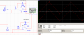
I will repost the Multisim schematic here so you wont have to go back a few pages in the thread. The resistor values seen in the Multisim schematic are not the same as in the breadboard and i have not updated the Multisim model to match the circuit on the breadboard as yet.
From testing today and throughout the past week i have found several things:
1) I am using R18 (200K POT) to vary the frequency of the waveforms and R3 (POT) to vary the amplitude.
I have found that at the lower amplitudes (lower than +/- 0.1 5) distortion starts to develop in the triangular and sine waves. There is also distortion at higher frequencies such as 2kHz to 5kHz:
This is the triangular wave at approximately +/- 0.5 V
This is the triangular wave at approx +/- 0.1V
Forgot to take a pic of the triangular wave at the lowest frequency (54.64 Hz) but it should look close to this:
This is the Triangluar wave at 2kHz
The same "tits" that were present in Bill's 555 function generator design are observed.
This is the sine wave at the lowest frequency (54.64 Hz)
At frequencies over 1.5Khz as seen below the wave gets distorted.
At 1.5Khz:
At 4.5Khz
This is the square wave with the amplitude at +1.4V, -1V. The Dc offset of 0.4 volts can be seen. The duty cycle is also off by a little.
This is the square at max frequency, approx 7kHz
At the lower frequencies the only problems with the square wave are the duty cycle and the Dc offset i mentioned earlier
What i want to know relates to the use of the two CMOS chips to generate the square wave. Is there a specific name for its configuration? I want to be able to add in something to change the pulse of the square wave, which will give me sawtooth waves.
I needed a non inverting Schmitt trigger, so I put two inverting types back to back.
I'm sure you mentioned it, but what op amp are you using? I'm kind of glad to see the "tits" are a constant, means it wasn't something specific to my wiring.
I am using a LM 324, i tried replacing it with the TL084 to see if any difference would be made in the DC offset but the waveforms were the same.
I put a LED at the input so it would light when on. I will configure it so that it comes off when the battery supply drops below 6 or 7volts so it can act as an indicator to change the battery.
Why are there "tits" on the square wave at higher frequencies (closer to 5kHz)
Are the "tits" shown on the triangle wave at higher frequencies a result of the "tits" of the square wave being integrated? Is it because of stray capacitance?
I read in Bill's 555 function generator thread that the "tits" on the triangle wave are as a result of the LM324 not being able to keep up with the square wave or that "the harmonics of the fast rise and fall times of the square wave are outside the bandwidth of the op amp".
Thanks! I did read something about that in Bill's 555 function generator thread where someone said to keep the integrator current lower by making R larger and C lower.
At the moment the PCB is to be designed on Monday 21st Dec.
I'll change the R and C in the breadboard and see how it works.
I tried using the Tl084 it did not help that much. I also read in Bill's function generator thread that the improper duty cycle of the square wave was due to the darlington configuration inside the 555 IC's. What aspect of the configuration causes the less than 50% duty cycle?
 Facebook
 Google
 GitHub
 Linkedin


") increase the input resistor of the triangle Opamp and decrease the capacitor to maintain the same frequency.
increase the input resistor of the triangle Opamp and decrease the capacitor to maintain the same frequency.