Help with fixing switches

Thread Starter

Darrin McCoy

Joined Sep 25, 2017
8
Hi everyone,

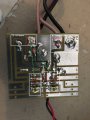
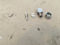
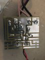
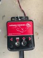
I am a new member and looking for a little help. It should be easy to fix but just need some assurance before trying anything. I am disabled and have a power lift that the momentary push buttons broke off. I am hoping I can replace the current switches with an aftermarket switch and just solder it to the board or jumper it from the wires. Please see attached pictures. Thank you for any help. I really appreciate it.
 

Attachments

Thread Starter

Darrin McCoy

Joined Sep 25, 2017
8
Sorry my computer shut down and I wasn't able to finish or upload more photos. This photo shows the following: how would wire in new switches correctly? Thanks again

Yellow - 3 prong switch locations
Red top right - 12v power
Red top left - 12v power to the motor
 

Attachments

#12

Joined Nov 30, 2010
18,224
Three terminals for a push button isn't normal. No pics of part numbers. No outside size measurements. No measurements of pin spacing. That's why nobody knows what switch to buy. I can tell the switches are low current because they drive a relay. Backside photo shows the switch pins near the edge of the board go nowhere, therefore, the other two pins are normally open, momentary.
 

Thread Starter

Darrin McCoy

Joined Sep 25, 2017
8
Sorry I realized I didn't provide much information. Hopefully the following is helpful

This is a Armstrong wheelchair lift in the picture and it works as follows.

1. I turn the unit on with the Toggle Power Switch on the end (Ref E)
2. Press and hold either power Up or Down (Ref C and D) and release when it is in correct position. There doesn't seem to be any limits or safety functions because it continues to run as long as the buttons are held in

Here are some more pictures and hopefully helpful information. When I connect the green lines the lift moves up and down accordingly. I can't get me mind around how the switches work. I appreciate your help. Please let me know what else I can provide that would be helpful.

Board
A - Input
A1 - 12v
A2- Gnd

B - D.C. Motor output
B1 - 12v
B2 - Gnd

C - UP Button switch - top to bottom of switch
C1 - 12v
C2 - Gnd
C3 - Post

D - Down Button switch - top to bottom of switch
D1 - 12v
D2 - Gnd
D3 - Post

E - Power On/Off Switch
E1 - 12v
E2 - Gnd


Switch sizes - 1/2 x 1/4 x 1
 

Attachments

Top