AlbertHall
- Joined Jun 4, 2014
- 12,345
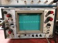
Yep, that would work.I suppose can feed some dc low voltage into the scope and compare what a dvm says.
Yes, can figure it out. On 1 v/div it reads exact voltage of course and 1.5v battery, it put a wave at 1.5 divs, @ 2v put it around 3/4 div.Yep, that would work.
When I hook my DVM to Cal OUT. It supposed to be .3v. I am getting 159.8mv on my older tester and newer about 160 mv. I suspect it is reading correctly being it is pulsed, being I getting 159.8mv two different testers.Yep, that would work.
make sense. so a square wave DC signal, full wave is both upper and lower? Is that the right? Mark is upper and space is lower?It is a 300mV square wave so it is 300mV for half the time and 0V for the other half so the dvm reads the average of about 150mV. The exact mark/space ratio will affect the DVM reading so it may be a little more mark than space.
Not necessaroily any of that!make sense. so a square wave DC signal, full wave is both upper and lower? Is that the right? Mark is upper and space is lower?
TV-V is TV-vertical. It's usually about line frequency. e.g ~60 Hz. B&W was the line freq. Color changed it very slightly.They have several smaller sq waves. I do not get that unless I increase my mV, to 20 or so. I was able to adjust the prob wave flat in the pict. Look at pictures and labels. The very first pic with sq waves, its showing 3 division, I accidentally had the tv-v on. It did not do anything when I moved it back to AC. Those 3 div in 1x mean anything?
Contact cleaner is OK. NO WD-40! De-Ox comes highly recommended.Most of the analog dials and switches show a lot of static on the screen. Sometimes I have to wiggle them. Can I use break cleaner or should I use something else?
In prder to mesure the DC amplitide, you have to do a GND check first. Set scope or probe to gnd and adjust the vert position so the trace is on a line. Then DC couple it. Multiply by 10 if you have to.Yes, can figure it out. On 1 v/div it reads exact voltage of course and 1.5v battery, it put a wave at 1.5 divs, @ 2v put it around 3/4 div.
With the digital tranistor Vce(sat) < 40 mV meaning, the calibrator output does not go below aproximately 40 mV. So, it could be 40 mV to 0.3 + 40 mV for 0.3V p-p. Use GND of the scope and position the GND trace on a line. Ten connect the calibrator. See if there is a DC offset. 150 mV is about 1/2 or the average. That's only 9.8 mV off? You need a 50% duty cycle as well.When I hook my DVM to Cal OUT. It supposed to be .3v. I am getting 159.8mv on my older tester and newer about 160 mv. I suspect it is reading correctly being it is pulsed, being I getting 159.8mv two different testers.
Seems like it is off quite a bit.
[/QUOTE]My turn, after everyone else was awake.
TV-V is TV-vertical. It's usually about line frequency. e.g ~60 Hz. B&W was the line freq. Color changed it very slightly.
3 div is 0.3 V p-p Your on a roll.
That second pic is showing the right voltage if your probe is in x1. The probe is not compensated correctly or you have the wrong probe. I'll look at your probe specs. It should look more like pic #1 except the V/Div knob should be 10x lower.
Contact cleaner is OK. NO WD-40! De-Ox comes highly recommended.
In prder to mesure the DC amplitide, you have to do a GND check first. Set scope or probe to gnd and adjust the vert position so the trace is on a line. Then DC couple it. Multiply by 10 if you have to.
With the digital tranistor Vce(sat) < 40 mV meaning, the calibrator output does not go below aproximately 40 mV. So, it could be 40 mV to 0.3 + 40 mV for 0.3V p-p. Use GND of the scope and position the GND trace on a line. Ten connect the calibrator. See if there is a DC offset. 150 mV is about 1/2 or the average. That's only 9.8 mV off? You need a 50% duty cycle as well.
Some TRMS, True RMS meters, can look at just the AC component or the AC+DC component. AC meaning time-varying portion.
How is your Calculus? On the scope, you will SEE peak to peak voltages.
Depending on your DVM and the waveform it's presented, you can get all sorts of values.
For sine waves up to about 400 Hz, you likely should get the RMS value on just about any DVM. One is older and the other is newer. Both had similar readings.
120 V RMS is +169 to -169 volts. Multiply 120 * sqrt(2) * 2 to get the p-p value of a sine wave.
Your other pics have the Volts/Div too low.
[/QUOTE]My turn, after everyone else was awake.
TV-V is TV-vertical. It's usually about line frequency. e.g ~60 Hz. B&W was the line freq. Color changed it very slightly.
3 div is 0.3 V p-p Your on a roll.
That second pic is showing the right voltage if your probe is in x1. The probe is not compensated correctly or you have the wrong probe. I'll look at your probe specs. It should look more like pic #1 except the V/Div knob should be 10x lower.
Contact cleaner is OK. NO WD-40! De-Ox comes highly recommended.
In prder to mesure the DC amplitide, you have to do a GND check first. Set scope or probe to gnd and adjust the vert position so the trace is on a line. Then DC couple it. Multiply by 10 if you have to.
With the digital tranistor Vce(sat) < 40 mV meaning, the calibrator output does not go below aproximately 40 mV. So, it could be 40 mV to 0.3 + 40 mV for 0.3V p-p. Use GND of the scope and position the GND trace on a line. Ten connect the calibrator. See if there is a DC offset. 150 mV is about 1/2 or the average. That's only 9.8 mV off? You need a 50% duty cycle as well.
Some TRMS, True RMS meters, can look at just the AC component or the AC+DC component. AC meaning time-varying portion.
How is your Calculus? On the scope, you will SEE peak to peak voltages.
Depending on your DVM and the waveform it's presented, you can get all sorts of values.
For sine waves up to about 400 Hz, you likely should get the RMS value on just about any DVM.
120 V RMS is +169 to -169 volts. Multiply 120 * sqrt(2) * 2 to get the p-p value of a sine wave.
Your other pics have the Volts/Div too low.
Like what I did in the photo?If the line is in the middle of the screen before you connect the probe, then that is 0V. The cal signal goes from 0V to 300mV - so from the that centre line 6 divisions upwards which takes the top of the waveform off the screen. Then you can adjust the Y position to move the 0V position to three divisions below the centre line and get your second waveform.
thanks, that helps...The 5mV/Div with a X10 probe gives 50mV/Div so 300mV gives 6 divisions deflection.
The time/div does not affect the voltage reading - it will spread out, or squish up, the waveform in the horizontal direction though.
Correct.thanks, that helps...
100mV @ 1x probe = .1V div
100mV @ x10 probe = 1V div
.5V @ x10 probe = 5V div
1V @ x10 probe = 10V div
1V @ x1 probe = 1V div
2v @ x10 probe = 20V div
2V @ x1 probe = 2V div
How come w/o adjusting anything except voltage to 10mV (from 5mV to 10mV cal setup) I get scrolling signal? If I back trigging level off a bit, it stops.Correct.
not sure I understand what you are saying. You said set 0 "near" bottom? Where is near bottom? I set it at, 3rd and 4th gratecule. Then you said to calibrate, this is not much different then I did before? The one picture 0 is set at 3rd div down and in the middle of the scale. The other pict, 0 is set at the bottom line and the wave is just below the measurement line. Where is this 40mV are you talking about the top of the square wave it is slightly above the gratecule (div) not sure if I am using the word gratecule right? Also, I am not sure where you wanted it lined up, I find it just below the increment is easier to see.What you did, is not EXACTLY what I wanted you to do.
Either set the coupling to GND or use the GND setting on your probe. You should have a straight line in auto-trigger. Move that line with the vertical position, so it's on a gratecule The calibration is aprox 0-0.3 V p-p, so set the 0 near the bottom of the screen.
Now apply the calibrate signal, DC coupled. You can muck with the level and slope controls. I THINK the bottom of the square wave will be slightly above the now invisible 0V reference that you arbitrarily set earlier. It could be as much as 40 mV.
There was someone in TX selling one of the textronic large scope with 100-200 tubes in it that was on cart with separate power supply. I think it was a 500 or 700 series scope. Its a true dual channel, it is used often to take pict. Nice to have for 170 bucks, to expensive to ship. In Carlson youtube video he has 3-4 models like that. very heavy, very nicely built machine.This
XYZ's of Oscilloscopes, Tektronix: http://ecee.colorado.edu/~mcclurel/txyzscopes.pdf
might help a lot.
At least your not playing with a dual trace dual time-base scope and it doesn't weigh 100 lbs.
Thread starter | Similar threads | Forum | Replies | Date |
---|---|---|---|---|
D | Help with a design | General Electronics Chat | 17 | |
D | Help needed, energy harvesting. | General Electronics Chat | 22 | |
J | Need help, a question about energy!!! | Homework Help | 5 | |
H | RF Energy Harvesting Project Help | Homework Help | 31 | |
D | MY idea for rf energy harvesting that needs help | Wireless & RF Design | 9 |
by Aaron Carman
by Jake Hertz
by Aaron Carman
by Duane Benson