 Facebook
 Google
 GitHub
 Linkedin
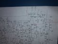
how do you get around testing a circuit with a full wave bridge?Compensation is only for 10x or greater probes. Metal screwdrivers can change the capacitance. There are plastic "alignment tools".
In a lot of switching power supplies are either full (120V) or 1/2 wave rectified (240 V) to start wit 3xx volts DC.
The two diode drops at the full-wave bridge cause major issues when trouble-shooting.
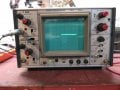
help with energy concepts 30820 oscilloscope
- Thread starter neospam
- Start date

") When I was probing pin 3 I noticed my scope was flashing like it was getting a signal, so I scoped the other plug-in prong and magic happen..
When I was probing pin 3 I noticed my scope was flashing like it was getting a signal, so I scoped the other plug-in prong and magic happen..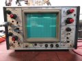


| Thread starter | Similar threads | Forum | Replies | Date |
|---|---|---|---|---|
| D | Help with a design | General Electronics Chat | 17 | |
| D | Help needed, energy harvesting. | General Electronics Chat | 22 | |
| J | Need help, a question about energy!!! | Homework Help | 5 | |
| H | RF Energy Harvesting Project Help | Homework Help | 31 | |
| D | MY idea for rf energy harvesting that needs help | Wireless & RF Design | 9 |


