help with energy concepts 30820 oscilloscope

Thread Starter

neospam

Joined Jan 13, 2020
110
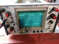
Hi all.. i recently purchased a ECI 30820, I believe it is a Iwatsu ss-5702 or close to it. No manual, no probs, 1st scope not sure it works. I purchased some probs and when I hook them up to the test lug, nothing happens.. small flat line go across the screen.

any help would be appreciated, I looking to go through and see what works and does not work. I have purached a working function gen, and was able to see some signal sq and saw.. the sine looked not right ghost looking and shaking.

p.s. this is my first scope, only used a auto scope..

any help is appreciated..
 

Thread Starter

neospam

Joined Jan 13, 2020
110
You will find links to the instruction manual and service manual here: https://www.staze.org/energy-concepts-inc-30820-20mhz-scope
thanks.. never could find 30820 anything..

thanks.. never could find 30820 anything..
just clicked on it and I have already DL those files for the ss-5702. It does not say much for adj probs, when I hook the prob onto the "sig V_out ring" for prob test I get nothing? when I move the prob around I see interference from the connection.

Can I feed it a signal from the function generator somehow and calibrate the probs?
 

tautech

Joined Oct 8, 2019
386
First make sure you have it set to Auto triggering then adjust the trigger level to get a stable trace.
10x probes can then be compensated with a 1KHz square wave for the best step response of the rising and falling edge.
Sometimes magnification (faster timebase) can allow for this adjustment to be made more precisely.

The most powerful tool in a scope is its trigger so learn its limits and how to use whatever features your trigger suite might have.
For the vast bulk of work use DC input and DC trigger coupling.
 

AlbertHall

Joined Jun 4, 2014
12,346
From the manual: I would add set the time/div to 1ms and set the triggering to auto. This is for a X10 probe. If you only have a X1 probe then set volts/div to 50mV.
1579428399225.png
 

Thread Starter

neospam

Joined Jan 13, 2020
110
From the manual: I would add set the time/div to 1ms and set the triggering to auto. This is for a X10 probe. If you only have a X1 probe then set volts/div to 50mV.
View attachment 197150
I tried this yesterday and did not get any signal to adjust the prob. I will try again today and get back. Was not sure I was doing it right, but followed the above and did not get any square wave. When I dvm/tested the .3v out for prob cal, I got mv reading. Will try again, I am wondering if the triggering is not working.

First make sure you have it set to Auto triggering then adjust the trigger level to get a stable trace.
10x probes can then be compensated with a 1KHz square wave for the best step response of the rising and falling edge.
Sometimes magnification (faster timebase) can allow for this adjustment to be made more precisely.

The most powerful tool in a scope is its trigger so learn its limits and how to use whatever features your trigger suite might have.
For the vast bulk of work use DC input and DC trigger coupling.
Excited to learn how to use this for my test bench.. trying to figure out what is all wrong with this if anything.

In the flow chart for trouble shooting, in the begining.. It say @ 14R50 (-10v) Well, I have no idea where 14R50 is located and did not find in manual. I will pop cover off and see if I can find some test points.
 

AlbertHall

Joined Jun 4, 2014
12,346
I tried this yesterday and did not get any signal to adjust the prob. I will try again today and get back. Was not sure I was doing it right, but followed the above and did not get any square wave. When I dvm/tested the .3v out for prob cal, I got mv reading. Will try again, I am wondering if the triggering is not working.
Do you get a single line across the screen which you can move up and down with the vertical position controls?
If so, try connecting a piece of wire from the calibrator output to the centre contact of CH1 input. You will need to set CH1 V/DIV to 50mV for this.
 

Thread Starter

neospam

Joined Jan 13, 2020
110
Do you get a single line across the screen which you can move up and down with the vertical position controls?
If so, try connecting a piece of wire from the calibrator output to the centre contact of CH1 input. You will need to set CH1 V/DIV to 50mV for this.
yes I get a single line across and does move up and down. I will try your suggestion next.

This is what I did so far.

I tired again and no signal. Took cover off to check cal out connection being ti felt lose. The solder connection was broke, I tested it from the plug in the circuit board and still nothing. I plugged my DVM into that point and no voltage. My outside cover says 0.3v for "cal out". I did find a lose nut in there floating around, not good.

I was wondering if my probs are ok. This is what I purchased for probs. The capacitance I am not sure if it was compatible. I do have a few cables now, bnc to bnc, bnc to alligator and to clips.


  • Band Width: 100MHz
  • Type: BNC
  • Rise Time: 3.5ns
  • Attenuation Ratio: 1:1 / 10:1
  • Resistance: 1MΩ / 10MΩ
  • Input Capacitance: 10X: 13-17pF
  • Input Voltage: 1X: 200Vp-p 10X: 600Vp-p
  • Operating Environment: 0-50°C
  • Compensation Range: 10pF-35pF

The manual says. - cannot fins the 1036 probe specs.. seems like the cap was 50pf.. not sure
 

Thread Starter

neospam

Joined Jan 13, 2020
110
Can you resolder the cal connection?

Try this using CH2 instead of CH1.
The broken connection was the test out put connection for calibration. I connected it by the plugin in the board. Still no square wave and connected it with wire to wire. I only get a straight line across screen, depends on the timing, but looks like a line or a bunch of dashes. There is some ghosting of a weird shape like small ovals connected together that you can hardly see. The straight line is very bright and has a small brighter center dot.

I do have a function generator if that helps with any diagnose. That is suppose to work, but the sine wave did not look right on the oscilloscope. It had a lot of ghosting, the square and saw pattern looked ok.

Can you resolder the cal connection?

Try this using CH2 instead of CH1.
the soldering I am going to wait if I can to see what else might be wrong. Looks like I will have to take some stuff apart to get in there to re-solder, not much room.
 
There's probably a X1/GND/x10 switch on the probe. Make sure it's not in the GND position. Many times, it covers avariable capacitance adjustment in x1. You cannot compensate a probe in the x1 position.

x10 actually means the input signal is attenuated by a factor of 10. In x2 the input Z of the scope is 1 M-Ohm in parallel with some capacitance and in the x10, compensated it's 10 M-Ohm resistive.

There are scopes with 50 ohm and 50 ohm/1M-Ohm switchable input Z.

just touching the input without a probe should show something at a high sensitivity.
 

AlbertHall

Joined Jun 4, 2014
12,346
I do have a function generator if that helps with any diagnose. That is suppose to work, but the sine wave did not look right on the oscilloscope. It had a lot of ghosting, the square and saw pattern looked ok.
So you get some vertical movement with the generator?
Do try CH2 and see if you get the same or different.
 

Thread Starter

neospam

Joined Jan 13, 2020
110
There's probably a X1/GND/x10 switch on the probe. Make sure it's not in the GND position. Many times, it covers avariable capacitance adjustment in x1. You cannot compensate a probe in the x1 position.

x10 actually means the input signal is attenuated by a factor of 10. In x2 the input Z of the scope is 1 M-Ohm in parallel with some capacitance and in the x10, compensated it's 10 M-Ohm resistive.

There are scopes with 50 ohm and 50 ohm/1M-Ohm switchable input Z.

just touching the input without a probe should show something at a high sensitivity.
do have it on x10. when I tap on the probe is make all kind of noise, see a bunch of vertical ghosting..
 

Thread Starter

neospam

Joined Jan 13, 2020
110
So you get some vertical movement with the generator?
Do try CH2 and see if you get the same or different.
channel 2 does the same as 1. When I feed the scope with bnc to bnc cable I do get square and saw pattern. Though the sine wave is not right, a lot of ghosting. This could be the generator, although everything was suppose to work.

Can I feed a square wave from the function generator "Hi out" to the scope ext trig to adjust the probe? not sure that would work.
 

AlbertHall

Joined Jun 4, 2014
12,346
channel 2 does the same as 1. When I feed the scope with bnc to bnc cable I do get square and saw pattern. Though the sine wave is not right, a lot of ghosting. This could be the generator, although everything was suppose to work.

Can I feed a square wave from the function generator "Hi out" to the scope ext trig to adjust the probe? not sure that would work.
OK. Foget the probe for the moment.
With the BNC cable and the sine wave, set the trigger to NORM and then adjust the trigger level and see if you can get a clean display.
 

Thread Starter

neospam

Joined Jan 13, 2020
110
OK. Foget the probe for the moment.
With the BNC cable and the sine wave, set the trigger to NORM and then adjust the trigger level and see if you can get a clean display.
Feed the FG into the EXT trig? or into scope 1 or 2?

see attached files, I just took these before you posted..
 

AlbertHall

Joined Jun 4, 2014
12,346
Given the square wave and sawtooth look OK I think the strange 'sine wave' is much more likely to be the generator than the scope.
Does CH2 look the same? If it does your scope is looking pretty healthy.
The strange image in the big picture is because the volts/div is set much too low and the time/div is also set very low.

Now try connecting the generator via the probe. Start with X1 and you should get the same on the scope as with the BNC cable.
If that looks OK, set the probe to X10, set the volts/div three clicks clockwise and you should get the same image again though it may have undershoot or overshoot. To fix that adjust the trimmer on the probe.
 

Thread Starter

neospam

Joined Jan 13, 2020
110
Given the square wave and sawtooth look OK I think the strange 'sine wave' is much more likely to be the generator than the scope.
Does CH2 look the same? If it does your scope is looking pretty healthy.
The strange image in the big picture is because the volts/div is set much too low and the time/div is also set very low.

Now try connecting the generator via the probe. Start with X1 and you should get the same on the scope as with the BNC cable.
If that looks OK, set the probe to X10, set the volts/div three clicks clockwise and you should get the same image again though it may have undershoot or overshoot. To fix that adjust the trimmer on the probe.
ok I will try that next.

sine.jpgI had some 1xKhz switch on (believe thats what it said). When I turned it off, sine wave cleared up.
 
Top