Facebook
 Google
 GitHub
 Linkedin
So a standard EIA 5% resistor is going to have three value bands?I would wire a pot in series with the existing resistor. That way, you can't burn out the LED regardless of where or how far you turn the knob on the pot.
Resistor color codes get real confusing because of changes that have occurred over the last 90 years or so. For that reason, when in doubt, use an ohmmeter to put you in the ball park. That will also help you determine about what value of pot to use to dial in the brightness.
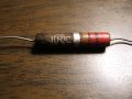
Note that the 1st band from the left in the photo is WIDER than the others. That signifies the FIRST band. On my monitor it looks like brown, brown, black, gold(?), gold(?). That translates to 11 ohm, 5% which is a standard EIA value. The last color band could represent either the temperature coefficient or the reliability. (REF http://www.resistorguide.com/resistor-color-code/). You would have to know the manufacturer of the resistor to know for sure.
While it would be nice if the first band were always wider than the others, or if the last band were spaced further apart than the others, there is no requirement or even widely accepted practice of doing either.
The first band is on the right side. It is a 3.3 kΩ, 1% resistor. This matches what the TS measured after removing it from the board.