Help with an audio amplifier circuit design

Thread Starter

Vman94

Joined Mar 11, 2019
6
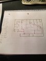
Hope everyone is doing fine, 1st time here so i dont know if I'm in the right place, i have an audio amplifer that I have to make for class, i chose a design and have to draw one for a PCB, if anyone can please confirm if my drawing is accurate to the actual design or not, please let me know, Thanks in advance!!!
 

Attachments

danadak

Joined Mar 10, 2018
4,057
Looking at datasheet there are some differences between the test
circuit in datasheet and your drawing, values of components.

Are those changes intended ?

Regards, Dana.
 

Thread Starter

Vman94

Joined Mar 11, 2019
6
Looking at datasheet there are some differences between the test
circuit in datasheet and your drawing, values of components.

Are those changes intended ?

Regards, Dana.
Do You mean the input connecting to C1?, other than that i didn't change any values of the components
 

crutschow

Joined Mar 14, 2008
34,286
What is the power supply voltage you will use?
How big physically is C7? What is its voltage rating?
The mounting holes for C7 seem a little close together.

RL is the speaker impedance, not a resistor in the circuit.
You should have output pads or terminals at the edge of the board for that.
 

danadak

Joined Mar 10, 2018
4,057
Do You mean the input connecting to C1?, other than that i didn't change any values of the components
My mistake, I was looking at the split supply schematic in datasheet, your
schematic does line up with single supply test circuit in datasheet.

Regards, Dana.
 

Thread Starter

Vman94

Joined Mar 11, 2019
6
What is the power supply voltage you will use?
How big physically is C7? What is its voltage rating?
The mounting holes for C7 seem a little close together.

RL is the speaker impedance, not a resistor in the circuit.
You should have output pads or terminals at the edge of the board for that.
i plan on using 9 volts as power supply, and i havent gotten the parts yet, i assume C7 is gonna be small, and i plan to use a 25v or 35v rating capacitor, other than ill space out the holes for C7 a little more, and make output pads for the RL, thanks
 

crutschow

Joined Mar 14, 2008
34,286
i plan on using 9 volts as power supply
For that voltage, the output power into a 4Ω speaker will be about 2W maximum.
i assume C7 is gonna be small
Assume?
You never assume a part size when laying out a PCB. :eek:
Why would you even do that?

Make a parts list and select the exact parts you will use, and then do the layout based upon their size and pad locations.
 

Thread Starter

Vman94

Joined Mar 11, 2019
6
For that voltage, the output power into a 4Ω speaker will be about 2W maximum.
Assume?
You never assume a part size when laying out a PCB. :eek:
Why would you even do that?

Make a parts list and select the exact parts you will use, and then do the layout based upon their size and pad locations.
I understand, i didnt get all my parts yet so that design is just a draft at this point, i shouldve mentioned that from the start, when i do get the parts ill redesign as accordingly
 
Top