Help with a series-parallel circuit

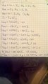
In post #16, you have a value of 1900.2534 Ω for R345||R2. If I work the problem of finding the equivalent value of parallel resistors "backwards" I can find the value of R345 that you used in the calculation of R345||R2. The result is that you used a value of 3190 Ω.

That is, 3190 Ω in parallel with 4700 Ω gives 1900.2534 Ω. But in post #12, it was pointed out that R3 + R4 + R5 = 3130 Ω. You have apparently misread your own handwriting and taken your handwritten value of 3130 Ω to be 3190 Ω somewhere on one of your sheets of paper.

WBahn mentioned that "your 3's and your 9's look an awful lot alike"; so much alike that you have fooled yourself somewhere in your handwritings.

So, to get a correct final result you need to correct your value for R345||R2.
 

WBahn

Joined Mar 31, 2012
29,978
There is another problem in my drawing. The resistance opposing the current until B is only R3 + R4, not R3+R4+R5.
You're correct. I was going off the diagram in your prior post and you have to go back to the original diagram to see the definition of Node B. Which underscores the value of being sure to consistently use definitions throughout a problem. Often times a particular node disappears as you simplify the circuit and has to be brought back later in the work. That's fine. But be careful to not reuse that same label anywhere else in the work on that problem otherwise you'll trick yourself into doing the wrong thing sooner or later.
 

WBahn

Joined Mar 31, 2012
29,978
There answer is technically incorrect.

If A is negative and B is positive, the Vab must be negative.

The E-book tends to be sloppy on some key things. This stems, I believe, from the starting point of wanting to use electron flow instead of conventional current and, like almost everyone that uses electron current, does it wrong. It's reflective of a mindset that relies on tracking magnitude and polarity separately instead of working with sufficient rigor that the math takes care of both naturally. It also handicaps you into being limited, for most people, to only working on small pieces of circuits (which is actually not too limiting in the end because we generally design circuits specifically so that this approach is feasible, albeit for different reasons) and so dealing with subsets of circuits having certain characteristics instead of being able to work with more general circuit families. This really comes out when working with higher-order reactive circuits -- circuits containing both inductors and capacitors.
 

Thread Starter

Hidden

Joined May 18, 2017
23
There answer is technically incorrect.

If A is negative and B is positive, the Vab must be negative.

The E-book tends to be sloppy on some key things. This stems, I believe, from the starting point of wanting to use electron flow instead of conventional current and, like almost everyone that uses electron current, does it wrong. It's reflective of a mindset that relies on tracking magnitude and polarity separately instead of working with sufficient rigor that the math takes care of both naturally. It also handicaps you into being limited, for most people, to only working on small pieces of circuits (which is actually not too limiting in the end because we generally design circuits specifically so that this approach is feasible, albeit for different reasons) and so dealing with subsets of circuits having certain characteristics instead of being able to work with more general circuit families. This really comes out when working with higher-order reactive circuits -- circuits containing both inductors and capacitors.
So this is why the Vab notation was wrong for the positive answer that i got. Could you send me to an article about magnitude and polarity, as I know almost nothing about these.
 

WBahn

Joined Mar 31, 2012
29,978
So this is why the Vab notation was wrong for the positive answer that i got. Could you send me to an article about magnitude and polarity, as I know almost nothing about these.
What I mean by "magnitude and polarity" is that some people will say that the voltage between A and B is 27 V regardless of whether A is more positive or B is more positive. They only talk in terms of the magnitude. Similarly, they will say that the current in the resistor is 12.4 mA regardless of which direction it is flowing. I do not support this approach -- it is sloppy and leads to too much miscommunication and fosters errors.

To be sure, in many instances the magnitude is all the information that we are trying to convey and when that is the case then that's reasonable. But in circuit analysis we almost always need to keep in mind that direction matters hugely. The best way to do this is to treat voltages and currents as signed quantities and to always be sure that what is meant by a positive value compared to a negative value is unambiguously clear -- usually through the definition of our terms as shown on a schematic -- either the arrow for a current or the +/- signs for a voltage difference. The voltage on a node is always understood to be the positive side of a voltage difference relative to whatever node we have chosen to call 0 V by making it our reference.
 

WBahn

Joined Mar 31, 2012
29,978
The second equation is incorrect.

What you are trying to do is apply KVL around a closed loop. You can think of KVL in a couple of different, equivalent ways:

The sum of the voltage drops around a closed loop is zero.
The sum of the voltage gains around a closed loop is zero.
The sum of the voltage drops around a closed loop equals the sum of the voltage gains.

In the last case, you have to be careful to go around the loop in the same direction for both sides.

On the left hand side you have Vab, which is either a voltage gain if you are going around the loop (with R1 and R5) counterclockwise or a voltage drop if you are going around the loop clockwise.
From the prior equation it appears that you want to count it as a voltage gain, but the circular arrow you draw says you are going counter clockwise. Take care to be consistent in your work.

Either will work, but you have to be consistent.

In the first case, you have gone counterclockwise and summed the voltage gains across the supplies on the left, so now you have to go counterclockwise and sum the voltage drops across the remaining elements on the right. In the case of both resistors when you go counterclockwise you are gaining voltage for the direction of the two currents given, so you have negative voltage drops.

Vab = -I1·R1 - I3·R5

In the second case, you have gone clockwise and summed up the voltage drops across the supplies on the left, so now you have to go clockwise and sum the voltage gains across the remaining elements on the right. In the case of both resistors when you go clockwise you are dropping voltage for the direction of the two currents given, so you have negative voltage gains.

Vab = -I1·R1 - I3·R5

Until you get comfortable with this, use one of the first two approaches by keep evening thing on the same side of the equation. Perhaps the surest way is to sum the voltage gains. If we go counterclockwise we would have

Vab + I1·R1 + I3·R5 = 0

Your last equation (at the bottom of your post, not in the image) is correct.
 

Thread Starter

Hidden

Joined May 18, 2017
23
As I see it I must remain "loyal" to the direction of current through AB(clockwise). But what about this example that we did in class. In the upper loop we take it clockwise, current I1 being positive. But then in the second one we take it clockwise again, contradicting with the direction of I1 that we used in the first case.
 

Attachments

WBahn

Joined Mar 31, 2012
29,978
The equation for each loop is independent of what direction you choose, either for that loop or any of the other loops. You could flip a coin before writing each equation. It just doesn't matter.

From a practical standpoint, you are less likely to make mistakes if you adopt a consistent method.
 

WBahn

Joined Mar 31, 2012
29,978
The second equation problem started because I simply did not assign a current direction through the AB power source. It is all clear now.
The direction that you assign a current direction to a voltage source doesn't matter. It's the direction that you are moving around the loop and whether you are summing voltage gains or voltage drops.
 

Thread Starter

Hidden

Joined May 18, 2017
23
One last question. When I3 enters the node B, considering KCL, it splits in 2 currents. So now through R5 goes only a fraction of I3 and through R1 only a part of I1 as it is no longer I3+I2. But in our equations we use the same "full" values of I1 and I3 and we get the same result. How?
 

WBahn

Joined Mar 31, 2012
29,978
I3 IS the current that goes through R5, now matter what happens at Node B. I3 is DEFINED at the current going clockwise through the upper branch, which includes R5.

Similarly, I2 is DEFINED as the current going clockwise through the lower branch, which happens to include R2.

Finally, I1 is DEFINED as the current flowing right to left through the middle branch, which includes R1.

These definitions are arbitrary. We could have flipped a coin in defining their directions. But, having defined their directions, KCL imposes a mathematical relationship between them, namely that the sum of currents leaving the node, (I1), must equal the sum of the currents entering the node, (I2 + I3).

You can think of it in terms of all kinds of analogies -- water flowing in pipes, people walking on paths, cars driving in tunnels.

At node B the flow from the upper and lower branches combine and total the flow going out into the middle branch.

But what if it turns out in reality that the flow coming down through the top branch does split and some of it goes out each of the other two? Let's say that 10 A of current is going downward through R5 and then splits so that 6 A continues downward through R2 while the remaining 4 A goes out to the left through R1. That's fine. Our analysis would simply conclude that I3 is 10 A, that I2 is -6 A, and that I1 is still I2 + I3 = 4 A. The fact that we get a negative value for a current (or a voltage) merely means that are arbitrary assignment of the direction didn't match the actual direction.
 

Thread Starter

Hidden

Joined May 18, 2017
23
Thanks for the explanation. If we got to negative currents, I solved a problem and one of the current ended up negative. Do I just write it as positive and change the assigned direction in my drawing?
 

WBahn

Joined Mar 31, 2012
29,978
Thanks for the explanation. If we got to negative currents, I solved a problem and one of the current ended up negative. Do I just write it as positive and change the assigned direction in my drawing?
You could do that, but then you would need to revise everything that uses that current to reflect the changed definition, including all of the work that led to the answer. Sometimes you will want to do that, such as if you are preparing documentation for a product, or a customer, or a publication. But usually you will just have the answer be a negative value in the direction that was originally defined. This is perfectly correct, unambiguous, and acceptable in most instances.
 
Top