Help with a series-parallel circuit

Thread Starter

Hidden

Joined May 18, 2017
23
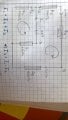
Hello! This is ex.6 in the worksheet about simple-parallel DC circuits. I tried something and I think I got pretty close. Now,
1. Is this method even correct?
2. Is there an easier way to do it?
3. I tried making R1 // R2 and then the total resistance in the resulting series circuit but it doesn't seem to work.
I'm an 8th grader so don't expect much. Thank you!
 

Attachments

wayneh

Joined Sep 9, 2010
17,496
I've taken the liberty of rotating your first image so that it's easier for folks to help you. Another piece of information that would help is the goal – what are you trying to solve for? (I assume it's the 3 currents?)

Does your solution satisfy the sum-of-currents rules you wrote at the bottom of the first image?

Circuit.png
 

WBahn

Joined Mar 31, 2012
29,979
First, welcome to AAC.

Thanks for showing your best attempt and big kudos for making an effort to be neat and organized and for labeling your diagram with the terms you are using in your work. It's like pulling teeth to get people twice your age to put forth that much quality effort, so you are off to a very good start.

There is definitely an easier way to solve this problem and the key is in the title of your post -- look for series/parallel combinations.

First, go for the low hanging fruit and combine any resistors that are clearly in series, meaning that whatever current flows in one must flow in the other.
Next, see if there are any that are in parallel and combine them, meaning that they are connected to the same pair of nodes. Coloring the nodes can help you spot these.

Keep repeating this process until you are either down to a single resistor connected to the battery or you can't combine any more resistors, in which case you can do what you are trying to do here or use some other techniques which you probably haven't studied yet to reduce the circuit further.

In this circuit, you can successfully reduce things all the way using a sequence of series/parallel reductions. Just looking very quickly and running estimates in my head, I expect the total resistance to be between about 1900 Ω and 2400 Ω, so call it about 2.1 kΩ. Once you have a solution see if you can understand how I came up with those estimates -- I'll be happy to explain it then.

Although you can do it using simple reductions, the approach you are trying to take should also work. So it is worth walking through it and seeing where you are going astray. I'll look at that in a bit.
 

WBahn

Joined Mar 31, 2012
29,979
3. I tried making R1 // R2 and then the total resistance in the resulting series circuit but it doesn't seem to work.
You can't combine R1 and R2 in parallel because they are not in parallel.

In order for two components to be in parallel they have to be connected to the same nodes and, therefore, have the exact same voltage across them at all times.

In this case R1 is connected between the bottom node (let's call it "ground") and Node A. R2, on the other hand, is connected between ground and an unlabeled node junction at the left hand side, the point being that it is NOT connected to Node A. In fact, the voltage across R2 is always 20 V more positive than the voltage across R2 (I'm using the voltage across each resistor as being the voltage on top of it relative to the voltage at the bottom).
 

Thread Starter

Hidden

Joined May 18, 2017
23
You can't combine R1 and R2 in parallel because they are not in parallel.

In order for two components to be in parallel they have to be connected to the same nodes and, therefore, have the exact same voltage across them at all times.

In this case R1 is connected between the bottom node (let's call it "ground") and Node A. R2, on the other hand, is connected between ground and an unlabeled node junction at the left hand side, the point being that it is NOT connected to Node A. In fact, the voltage across R2 is always 20 V more positive than the voltage across R2 (I'm using the voltage across each resistor as being the voltage on top of it relative to the voltage at the bottom).
I thought that nodes are intersections of at least 3 circuit element. I considered A just as a point of reference in the circuit.
 

WBahn

Joined Mar 31, 2012
29,979
Your work is fine except that your last equation messes up the sign. You are picking up some roundoff error because you are only recording your results to two significant digits.
 
Last edited:

WBahn

Joined Mar 31, 2012
29,979
I thought that nodes are intersections of at least 3 circuit element. I considered A just as a point of reference in the circuit.
A node with at least three branches is an "essential node", but a node is basically any place that you could point to and measure a voltage. In performing circuit analysis you need to apply KCL at all essential nodes -- you don't need to consider non-essential nodes because KCL is trivially satisfied there.

You can pick any node you want and call it the reference.
 

Thread Starter

Hidden

Joined May 18, 2017
23
A node with at least three branches is an "essential node", but a node is basically any place that you could point to and measure a voltage. In performing circuit analysis you need to apply KCL at all essential nodes -- you don't need to consider non-essential nodes because KCL is trivially satisfied there.

You can pick any node you want and call it the reference.
So that means that the definition of parallel and series doesn't consider essential nodes only, but any node?
 

WBahn

Joined Mar 31, 2012
29,979
So that means that the definition of parallel and series doesn't consider essential nodes only, but any node?
If two components are in series, then the node connecting them CANNOT be an essential node. They are only in series if whatever current is flowing in one component MUST be the same exact current that flows in the other. If the node between them is an essential node, the current can enter/leave that node from the additional branches resulting in the currents in the two components not being the same.
 

Thread Starter

Hidden

Joined May 18, 2017
23
WP_20170518_21_39_21_Pro.jpg This is all I could come out with. And it's wrong(after some calculations). I don't seem to realize where series and parallel sections are.
 

LesJones

Joined Jan 8, 2017
4,174
I think you have made an error adding R3 + R4 + R5 1000 +1500 + 630 = 3130 not 3430.
Moving R2 above the middle line (The one with the battery in it.) may make it clearer which is parallel and which is series.
 
After a few lines in your calculations, you have:

20 = 3130 I1 - 3130 I2 + 250 I1

From that you then get:

20 = 3440 I1 - 3130 I2

How did you get 3440 I1? It looks to me like you were adding the two terms in I1, but they don't add up to 3440 I1.
 

WBahn

Joined Mar 31, 2012
29,979
View attachment 127095 This is all I could come out with. And it's wrong(after some calculations). I don't seem to realize where series and parallel sections are.
In addition to adding the three series resistors and getting the wrong answer (which I think is due to just a little bit of sloppiness in writing your numbers -- your writing and drawings are quite neat over all, so just take a bit more care in writing your numbers so that it is clear exactly what each digit it) at the bottom you treat the three remaining resistors as if they are in parallel. As before, they are ONLY in parallel if they have the exact same two nodes on each end of each one of them.

Remember what I recommended -- color the nodes:
Edit_2017-05-18_1.jpg

R345 = R3 + R4 +R5

R345 and R2 are in parallel because they are both connected to the red and the blue node.

R1 is NOT connected to the blue node, it is between the red and the green nodes. Therefore it is NOT in parallel with the other two. So combine just those two.

Also, in your equation at the bottom you used R1, R2, and R3 in the parallel resistor formula. But R1, R2, and R3 are not the resistors that you are referring to. Do NOT use the same designator for two different things in the same problem -- it is asking for disaster to strike.
 

WBahn

Joined Mar 31, 2012
29,979
Is the exercise you are trying to work one of the ones on AAC? If so, I can't find it. Could you please post a link to it?
 

Thread Starter

Hidden

Joined May 18, 2017
23
Everything is now done and I understood the problem. Thank you all for supporting me and understanding my mistakes. Now one last question. In the first drawing on this particular attachment there is a series circuit. As we add R2 2 nodes appeared and this is no longer in series. Voltage across R345= to the voltage across R2 and knowing R345 and R2 we can solve for I3(across R345) and then I2(across R2). Why is there the current in the first(series circuit) = to I1( current in the "main" branch). Once again, thank you all and I'll be sure to solve other exercises, as this is my first serious one.
PS: The thing that really screwed me over was that battery put between the two essential nodes.
WP_20170519_15_49_26_Pro.jpg
 

WBahn

Joined Mar 31, 2012
29,979
I'm not quite following what you are asking or what you are having confusion about, so this may not help.

Also, and I'll get to this later, you still have a sign error in your final result.

Consider the branch with the voltage source in it:

branch.jpg

Can you tell which of the two circuits this is from (based on the content of the circuit, not on things like a stray pencil mark)?

If you connect this circuit fragment to two different external circuits that are equivalent, then this branch has no way of knowing which of the two it is actually connected to -- that's what defines the equivalence of the two circuits. That being the case, the voltage different between the two terminals, Vxy = Vx - Vy, and the current in the branch, Io, have to be the same in either situation.

In the first circuit the external circuit requires that whatever current Io is, that that same current flows up and around the top branch. In the second circuit, the same exact Io has to flow, but now it splits and some of the current goes up through the top branch and some goes down through the bottom branch. How much goes each way is determined by the requirement that the voltage across the two branches has to be the same Vxy as above.

Now for your lingering sign error.

In the top diagram you define I1 as the current that is flowing left to right in the top branch and conclude that it is 9.301 mA (and your 3's and your 9's look an awful lot alike). This is then the current that is flowing right to left through the lower branch.

In the bottom diagram you define I1 as the current that is flowing left to right in the middle branch. But then you use the result from the top diagram and set it equal to 9.301 mA despite the fact that you have redefined it to be flowing in the opposite direction!

Signs matter -- in a very real sense they are THEY most significant digit in a value. Neglect the sign information when you try to jump start a car and the battery may well explode in your face. You must make sure that the sign of your answers or consistent with the definitions of your reference directions.

You are trying to find Vab. This uses double-subscript notation which means the voltage at Node A relative to the voltage at Node B, or Vab = Va - Vb. It is critical that you realize that Vab and Vba are NOT the same thing.

You are being VERY sloppy with this information.

You calculated that V3452 = 17.6452 V. But you never defined what the reference polarity was. Since this is the voltage across a resistor, there is what is known as the passive sign convention which assigns the positive terminal of a resistor (or other passive device) to be the terminal that the reference current (I1 in your top diagram) enters. That means that V3452 is the voltage of the leftmost node relative to the rightmost node -- which agrees with the polarity that has to be the case in order for current to flow left to right through that resistor.

But then in the bottom diagram you define the current I2 to be the current flowing right to left through R2 but use the voltage 17.65 V to find the current in R2 and come up with a current flowing right to left.

Does this make sense?

If you always define your voltages and currents consistent with the passive sign convention, and if you never use the same variable for two different things in the same problem, and if you clearly define the polarities of your voltages and currents, you will almost never make these kinds of easy to make, hard to find silly errors.

In your case, ALL three of the currents in your bottom diagram are actually negative.

In finding a particular voltage, say Vab, it can help to draw (at least mentally) a battery equal to Vab between the two nodes and then write a suitable loop equation.

Edit_2017-05-19_2.jpg

We can now easily write three loop equations, any one of which will let us solve for Vab.

Vab + 20 V + I3·R345 = 0
Vab + 20 V + I2·R2 = 0
Vab - I1·R1 = 0

We also have

I1 = I2 + I3

This gives us four equations and four unknowns, I1, I2, I3, and Vab.
 

Thread Starter

Hidden

Joined May 18, 2017
23
I am really sorry about the current directions and I know they are important but at the moment I was only carrying about the numbers and the operations.
 

WBahn

Joined Mar 31, 2012
29,979
I am really sorry about the current directions and I know they are important but at the moment I was only carrying about the numbers and the operations.
But if the directions are wrong, then the numbers and the operations can't be right.
 

Thread Starter

Hidden

Joined May 18, 2017
23
There is another problem in my drawing. The resistance opposing the current until B is only R3 + R4, not R3+R4+R5.
 
Top