 Facebook
 Google
 GitHub
 Linkedin
Hello.
Could you please help me out ?
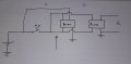
I am trying to build a circuit that would use two push button in order to turn ON and OFF a system.
When pressing the ON button, it will be latched using a relay.
I would like that when the OFF button is pressed, a timer from a 555 will count back some time, and when it is done, the system will shut down.
I would like to add a relay where the arrow is showing, and for that relay to be activated from the 555.
I tried a few times but could not get it to work.
How should I build the circuit ?
Thank you
Could you please help me out ?
I am trying to build a circuit that would use two push button in order to turn ON and OFF a system.
When pressing the ON button, it will be latched using a relay.
I would like that when the OFF button is pressed, a timer from a 555 will count back some time, and when it is done, the system will shut down.
I would like to add a relay where the arrow is showing, and for that relay to be activated from the 555.
I tried a few times but could not get it to work.
How should I build the circuit ?
Thank you
Attachments
-
 1.5 MB Views: 30


")


