Facebook
 Google
 GitHub
 Linkedin

Hi, I'm just looking for some guidance on a project I'm currently working on for university - I'm a physics student.
The aim of my project is to use Arduino (then Raspberry Pi & more expensive micro controllers) to build intelligent control circuits which will be used in line with some of the laser systems we have at the university. The trouble is that electronics has always been my weakest subject - I chose this project so that I would learn something.
Initially I was asked to build a simple temperature sensor which I managed okay. I used an AD592 interfaced with the Arduino and was able to obtain accurate (for what we need) readings.
Now I have been asked to incorporate a Peltier Heat Pump/Cooler to control the temperature of a laser diode mount based on the temperature read from the sensor.
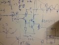
My supervisor drew me a quick sketch on the white board for the load part of my circuit (see below) with a couple of transistors. I have been doing some research online and realise that this is a push-pull amplifier configuration that can be used to both heat and cool the element.
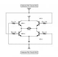
I drew the second attachment based on his original sketch. I added the names to the transistors that I'm using and have replaced the Peltier component with a DC motor so that I can easily tell if I have it working (in principle I don't think it should really make a difference what I use as a load).
I was wondering if anyone could help me with the values of the 3 resistors? How do I go about selecting these values? The motor I currently have will run on 10V DC.
Also, I should probably add a diode in with the 1k resistor to stop any high current going back into the Arduino. Am I right?
Any guidance you can offer is much appreciated. I hope this hasn't been too long. Thanks for reading!!
The aim of my project is to use Arduino (then Raspberry Pi & more expensive micro controllers) to build intelligent control circuits which will be used in line with some of the laser systems we have at the university. The trouble is that electronics has always been my weakest subject - I chose this project so that I would learn something.
Initially I was asked to build a simple temperature sensor which I managed okay. I used an AD592 interfaced with the Arduino and was able to obtain accurate (for what we need) readings.
Now I have been asked to incorporate a Peltier Heat Pump/Cooler to control the temperature of a laser diode mount based on the temperature read from the sensor.
My supervisor drew me a quick sketch on the white board for the load part of my circuit (see below) with a couple of transistors. I have been doing some research online and realise that this is a push-pull amplifier configuration that can be used to both heat and cool the element.
I drew the second attachment based on his original sketch. I added the names to the transistors that I'm using and have replaced the Peltier component with a DC motor so that I can easily tell if I have it working (in principle I don't think it should really make a difference what I use as a load).
I was wondering if anyone could help me with the values of the 3 resistors? How do I go about selecting these values? The motor I currently have will run on 10V DC.
Also, I should probably add a diode in with the 1k resistor to stop any high current going back into the Arduino. Am I right?
Any guidance you can offer is much appreciated. I hope this hasn't been too long. Thanks for reading!!
Attachments
-
 293 KB Views: 80
-
 44.2 KB Views: 139