
 Facebook
 Google
 GitHub
 Linkedin
Hello all,
I am looking to build this circuit (Voltmeter/Ammeter)
http://electronics-diy.com/70v_pic_voltmeter_amperemeter.php
But I do not understand how this part works
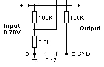
I understand the voltage divider and how that goes to the uC. But I'm confused by how the shunt resistor being used for current sensing in this diagram, mainly where is the current flowing in this diagram? Can someone help? I'm seeing two grounds here and that is confusing me. The website says "Current sense 0.47 Ohm shunt resistor is connected in series with load at the negative voltage rail and is passed to microcontroller chip through 100K resistor." How is current flowing up from ground to the micro in this way? Am I reading this wrong?
Sorry for such a noob question. I just need a little jump start. I would like to understand how this works before building it.
I am looking to build this circuit (Voltmeter/Ammeter)
http://electronics-diy.com/70v_pic_voltmeter_amperemeter.php
But I do not understand how this part works
I understand the voltage divider and how that goes to the uC. But I'm confused by how the shunt resistor being used for current sensing in this diagram, mainly where is the current flowing in this diagram? Can someone help? I'm seeing two grounds here and that is confusing me. The website says "Current sense 0.47 Ohm shunt resistor is connected in series with load at the negative voltage rail and is passed to microcontroller chip through 100K resistor." How is current flowing up from ground to the micro in this way? Am I reading this wrong?
Sorry for such a noob question. I just need a little jump start. I would like to understand how this works before building it.






