Help to improve this filtering circuit

Thread Starter

Baphomet12

Joined Jan 31, 2017
34
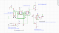
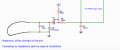
The following shows the diagram for a sensing and filtering input of a break-wire alarm. The CMOS logic input is held low by the break-wire ( 60ft long) and goes high once the wire is broken. The triggering voltage for the logic high is around 6V when Vcc is 10v. R2 needs to be very high to minimise the current consumption, as the circuit is battery operated. I'd like any suggestion and opinion to help to improve this circuit to maximise immunity against RFI, EMI and other induced noises. Would the addition of an inductor improve the function? Regards
 

Attachments

#12

Joined Nov 30, 2010
18,224
C6 is in charge of RF noise control. RC time constant of 25 micro-seconds? That's pretty fast response, the kind that causes false alarms. I wouldn't hesitate to increase that to 1nf but you have to stay small and ceramic or the frequency response won't work for radio frequencies. D1 also stops any positive noise voltage from getting into the CMOS. Then you have C2 to slow things down. 50 milliseconds? That's more like it. Leave that in as a high frequency ceramic capacitor, but you could add a whole uf in parallel with it to slow things down to a few tenths of a second. Nobody is going to make off with the goods in 1/2 second.

I wouldn't use a bifilar wire. Sure, it's easy to install, but McGyver could defeat that with a paper clip.
 
Last edited:

Thread Starter

Baphomet12

Joined Jan 31, 2017
34
Hi, thanks for the suggestion. So, overall you just recommend adding a 1uF cap? The Break-wire is very hard to see as it's in the grass 20cm above the ground and very thin (0.1mm). The device is mostly for the scaring of the wild boars and it fires a squib ( firecracker). I found a picture of a security device with same function. The silver blocks are polyester caps, 50nF. As you can see there is a transformer in there. Is it a line filter transformer acting like an inductor?
 

Attachments

Last edited:

#12

Joined Nov 30, 2010
18,224
very thin (0.1mm).
That's 38 Gauge wire. I used 30 Gauge when I was doing a permanent installation. Trying to be reliable across time and warn the humans, "If you break this, I will know immediately." Better to discourage an attack than detect it.;)
you just recommend adding a 1uF cap?
That would be right for what I was doing, but if you slow the response down that much, the pig will have enough time to realize he touched something before the squib fires. You have to keep the time down below 0.1 second in order for a creature to not be able to tell the difference between the "twang" on his leg and the fireworks. That 50 milliseconds on the second capacitor seems right for what you're doing.
Is it a line filter transformer acting like an inductor?
I don't know.
 

Thread Starter

Baphomet12

Joined Jan 31, 2017
34
Thanks, what sort of frequency this device will be more susceptible to ? Is it about frequency itself or the amplitude of the wave? The amplitude could be reduced by increasing R1 which in this case 500k should be high enough.
 

#12

Joined Nov 30, 2010
18,224
Thanks, what sort of frequency this device will be more susceptible to?
What kind of frequencies do you have in mind for places where wild pigs roam?
Is it about frequency itself or the amplitude of the wave?
Is what about frequency or amplitude? The interference this was designed to be immune to?
The amplitude could be reduced by increasing R1 which in this case 500k should be high enough.
There is no R1 in your drawing.

I can't figure out what the goal is. What is "better"?
I already mistakenly wandered off into how to design this for humans. I'm tired of hypotheticals and guessing.
Start at the beginning. Why do you want to improve the filtering? What kind of problems are happening?
 

Thread Starter

Baphomet12

Joined Jan 31, 2017
34
As I said in the first post RF, EMI, and also add to the list, cellular high frequency. The sort of frequencies that are around us in these days and most electronics are designed to have degree Of immunity. To rephrase my previous question, given the nature of the device, what frequency range would the device be more susceptible to? The R1 should be R8, that was a typo. My overall goal is to decrease the false trigger, if there would be any, by still optimising the sensing and filtering section further using additional components or using alternative or improved filter design. For example, it was suggested to include a 100p cap with very short legs parallel to TVS, to suppress cellular range frequencies more. I hope you have a better understanding of the requirements now.

It may not be very relevant, but I've included the complete diagram here so you get more familiar with the function of the device.
 

Attachments

Last edited:

#12

Joined Nov 30, 2010
18,224
to decrease the false trigger, if there would be any,
The fact that you can name several frequency bands does not mean they are a problem. Your circuit has 10 times the quality I used for a burglar alarm. After that, I don't have the skills to analyze the free air power levels required to "false trigger" that circuit. If you want that answer you will have to name the length of the wire, and how much it is not perfectly twisted along it length to equalize (nullify) the pickup of interference.
 

Thread Starter

Baphomet12

Joined Jan 31, 2017
34
The wire length is 20m with the thickness of each wire 0.06-0.1mm. Since I couldn't find commercially available twisted type. I'll fold a 40m length into half and I'll connect one end of the wire pair to a stationary object and by using a power drill start twisting at other end until a reasonable twist rate is achieved. Finally, It will be painted dark green. I think the best way to test any system is to put them in the actual use to see how it performs over a time period.
 

#12

Joined Nov 30, 2010
18,224
That's exactly what I was thinking. Try actually building it before you go chasing imaginary problems. You can pre-worry a thousand things that don't cause any problems. You can spend hundreds of hours analyzing the parameters which the designer already considered when he designed this. Or you can build the dam thing and see if it works.

I got sucked in to chasing another imaginary problem.:(
 
Last edited:

Thread Starter

Baphomet12

Joined Jan 31, 2017
34
Yes I agree. I ordered the pcb for the circuit yesterday. Unfortunately, I spotted a problem this morning which I missed before. If you look at the complete diagram you see Q1 which is acting like safety valve. It's a PNP and normally it's reversed biassed to cut off i.e positive voltage at base and it activates when the break wire is not connected properly. The problem is I didn't know the reverse Vbe breakdown of most transistors were 5-6v. In this case the voltage at base of Q1 is 8.5v, which is higher than it can tolerate. I am scratching my head now to how to overcome this issue. I should had used voltage divider.
 
Last edited:
Top