help to convert a AC stepping down transformer to switching supply

Thread Starter

rolo95

Joined Dec 25, 2017
18
Guys,
this is my 1st post
I just scored 3 pieces of DJ Lights ( Chauvet Intimidator 1 ) around 10 years old

Those are called scanners ( the ones that have the moving mirror in X/Y Axis )

it is something like this
https://www.hifisoundconnection.com...r-LED-60W-Color-Gobo-Light-INTIMSCANLED300-RS
but mine are the older 1st edition models
not LED engine inside but ELC/3 24V 250 watts dicoroic Lamp

https://www.bulbamerica.com/product...-mr16-250w-24v-gx5-3-3400k-halogen-light-bulb

the things are HEAVY !!!
so i opened one and the CULPRIT are a HEAVY AC to AC step down tranformer
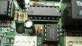
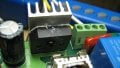
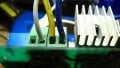
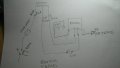
the thing have 2 pair of wires in labeled 0 - 120 for 1 pair and same for second pair

out are 3 wires.... 0,12vAC and 24VAC
24 are for the lamp
and the 12vac is for the logic board who take the DMX signals and feed 4 servos stepper motors
2 for the mirror x/y steper motor and 2 for the GOBO and COLOR wheels

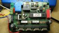
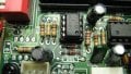
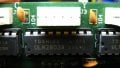
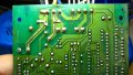
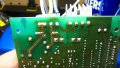
main board have Rectifier bridge
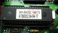
it have a Microcontroller and 4 servo contoller chips and DMX chips

anyway.... i removed the Transformer and want to install a switching supply
or something that will make the fixture to weight half of the original weight with the Giant IRON step down AC/AC xformer

Any ideas ?
i was looking in to feed DC in to the circuit whew the tranformer wires enter the board as current will flow just to one side of the rectifier bridge
minus the voltage drop ond the Diodes

so i dont know if i will feed 14.4 VDC where 12vAC was feed

is there any switching gizmos that will take AC and step down to AC but without the LINEAR Tranformer thing ?
what would be options to do this?

someone in youtube posted a video of a Scanner fixture that used the same 24V 250watt elc3 lamp and converted it to LED engine( those 100w big led waffers)
but he dont removed the tranny , just added a switching supply to the led engine

i removed the tranny and want to add something much lighter that can power the board and light
or 2 switching supplies , one for each

or use
some GX5.3 2-Pin
MR16 Bulb of another voltage
is there any Mr16 120vac bulbs ?
btw 250 watts at 24v are like 10 amps right ?

any pointers will be appreciated
Happy Holidays
Rolo
 

Thread Starter

rolo95

Joined Dec 25, 2017
18
ohh, i need 250 watts
and i dont want to get in to the LED engine swap , too much custom drilling and modding inside the case
 

dendad

Joined Feb 20, 2016
4,451
You need to get the circuit to see If DC is ok to feed it with. For example, if the lamp is switched on and off by an SCR or TRIAC circuit, DC will not work.
And DC may be OK to feed the other power supply or may not. It all depends on the circuit configuration. Do you have a circuit digram?
You could trace the power supply part of the circuit out to see. If for instance, the 12V AC is just rectified and fed straight to a regulator and nothing else, DC of the correct value could feed to that regulator or if it is less that 12V out, into the bridge in place of the AC or to the bridge output. But you do need to find out what the circuit is first.
Depending on the circuit, you may be able to use a 24V switcher to run the lamp and feed another gegulator to supply the low volts too. But get some circuit info!
 

Thread Starter

rolo95

Joined Dec 25, 2017
18
You need to get the circuit to see If DC is ok to feed it with. For example, if the lamp is switched on and off by an SCR or TRIAC circuit, DC will not work.
And DC may be OK to feed the other power supply or may not. It all depends on the circuit configuration. Do you have a circuit digram?
You could trace the power supply part of the circuit out to see. If for instance, the 12V AC is just rectified and fed straight to a regulator and nothing else, DC of the correct value could feed to that regulator or if it is less that 12V out, into the bridge in place of the AC or to the bridge output. But you do need to find out what the circuit is first.
Depending on the circuit, you may be able to use a 24V switcher to run the lamp and feed another gegulator to supply the low volts too. But get some circuit info!
Dendad,
i dont have schematic of the light circuit as Chauvet is very hermetic to let those go, i have called them and they wanted me to buy their new LED version of the lights instead of giving me a service schematic , the board itself is not that complicated, there is no SMD's on the board
i can remove it and take some pics of it

looks like the lamp have a relay, as it is wired in series , one pin of the lamp to the 24vac on the transformer and the other lead of the lamp goes to the board , along with the 0VAC and 12VAC wires coming from the transformer

As far as i know Chauvet is just a reseller like American DJ ( ADJ ) their lights are made in Guangzhou, China
that part of China is like an industrial park with all the major factories were robotic and industrial LED lights are made
and i found that digging in to google on the import export sea paperwork orders

Obviously there are different levels of QC, being the sloppiest companies who sell for less
at least those that Chauvet and ADJ uses to make their stuff are pretty decent QC wise

But, wish i can contact the original manufacture who can furnish me a schematic or service manual

I will try again with Chauvet to see if they have some or i get lucky with a tech who dont mind to "break" some rules

Meanwhile i can snap pix of the thing and post them
What you think
Rolo.
 

dendad

Joined Feb 20, 2016
4,451
It could be a good learning experience to try to trace out the power supply circuit yourself. Have a go at that and post your results and the board picture too. Depending on how the 2 power supplies are interconnected, you just may get away with using one switch mode supply. But you do need to research that to avoid the magic smoke effect!
Tracing the circuit will help us tell you is it is possible. Without that, you do run a risk of frying it and that would not make you very happy!
 

Thread Starter

rolo95

Joined Dec 25, 2017
18
It could be a good learning experience to try to trace out the power supply circuit yourself. Have a go at that and post your results and the board picture too. Depending on how the 2 power supplies are interconnected, you just may get away with using one switch mode supply. But you do need to research that to avoid the magic smoke effect!
Tracing the circuit will help us tell you is it is possible. Without that, you do run a risk of frying it and that would not make you very happy!
Dendad,
I will try to post something tomorrow
i have 2 more Light fixtures that are unmodified and working
what i just did a couple of hours ago at lunch time was to use a Fluke Clamp amp meter to measure the current draw of the original circuit

I found that it have a Relay on the 24VAC line in series with the light bulb as when you plug the fixture to the Power outlet it start to move the servos from the 2 rotating plates and the 2 X/Y that move the mirror to a fixed end limit position, that takes around 10 seconds
following that i hear a CLICK and then the lamp turned on

Before the lamp turn on i measure 0.40 Amps of current flowing trough the power cable ( i remove the outer jacket of a IEC power cable, same ones as the computer power supplies uses ) and expose the 3 inner conductors that where color coded as Green for ground black for Hot and white for neutral

when the lamp turned on i measured 2.08 amps and with the lamp on and all 4 servos (stepper motors ) operating i measured 2.15 amps
that means that the lamp itself draws around 1.68 amps

If i remove the 24v lamp and install a 120v lamp same wattage ,i can completely eliminate the 24vac need of the circuit
and we concentrate just on the 12vac input on the board

let me remove it tonite and i will report back tomorrow
i will snap some pics of the original tranformer along with the labels on it

and will snap some pics of the PCB top and bottom
i will try to put a strong light on the oposite solder side of the board so i can see how the traces go from the top

Many thanks for the support Dendad
Rolo.
 

Thread Starter

rolo95

Joined Dec 25, 2017
18
Ok, i snapped some pics of the board, BTW the board have a date on it and is dated 2013, so that fixture have at least 14 years !!!
back in the days electronics was made to last, nowdays they have a 2-3 year lifesspan

i assume that the bridge chip output + polarity is on pin 4 , pin 4 feeds pin 1 on the Positive 7805 Voltage regulator
so pin4 on the bridge must be positive
 

Attachments

dendad

Joined Feb 20, 2016
4,451
Can you check the power transformer connections. Is it like this?
LightControl.jpg
I have swapped a couple of wires. The blue and yellow.
Otherwise, the lamp is 12V, not 24V as far as I can tell.
 

Thread Starter

rolo95

Joined Dec 25, 2017
18
Can you check the power transformer connections. Is it like this?
View attachment 142608
I have swapped a couple of wires. The blue and yellow.
Otherwise, the lamp is 12V, not 24V as far as I can tell.
I forgot to attach the sticker on the transformer
yellow is 0V , blue 12v and Red 24v
red goes to one pin of the lamp socket and the other pin of the socket goes to the board lamp is in series
that is the white lead you see next to yellow
and yes!!! i swapped the blue and yellow, it is like you drawed!!! how do you figure it out !!

but lamp is 24v 250 watts ELC/3

https://www.bulbamerica.com/product...-mr16-250w-24v-gx5-3-3400k-halogen-light-bulb
Rolo

1xformer.jpg
 
Last edited:

dendad

Joined Feb 20, 2016
4,451
You could try something like this...
LightControl2.jpg
But the 12V regulator may need to be higher volts, like 13.8V or 15V .
There will be a 1.5V loss in the bridge rectifier. Still, it may work. I don't know how tolerant the motors and controls are.
A 24V to 12V (adjustable) converter like this is one option...
https://www.ebay.com.au/itm/DC-DC-S...763551?hash=item236154339f:g:Z0sAAOSwX~dWn5M8

If you have access to a separate 12V supply, try that. Just make sure the current rating is a few amps. I don't know what is needed with all the motors running. But putting a supply with a current meter on it for a test would be a good idea.

And as for working out the wires, I just traced the circuit out and compared it to what you had posted. The relay contact had the yellow wire feeding it and the other side if the relay was the white wire to the lamp. As you said the lamp was 24V, it was most likely then that the yellow was 0V.
Tracing circuits can be very confusing so well done for you efforts. I've had a little more experience I reckon, but even so, I still make lots of mistakes too.
 

Thread Starter

rolo95

Joined Dec 25, 2017
18
So, a 24VDC supply with a DC to DC step down board for the 12V one ?
can i use use a 24VDC and feed both inputs as the 12v will be converted to 5 with the 7805 regulator

and how many amps ? i measured 2.4amps max but at the 120 VAC side
and i dont know how that get converted at lower voltages

So a switching 24vdc supply ? how much amps ?
 

dendad

Joined Feb 20, 2016
4,451
If you measure the AC current on the blue wire, it will give you an idea of what the 12V needs to supply.
No, don't feed the 24V into the 12V. The 12V is also used to run motors, and maybe more. Whatever plugs into the X,Y, C, G and probably the other connectors as well.
The total power will be over 250Watts so I'd go with quite a bit more as a cold lamp draws a very high start up current.
The transformer is 280VA, but it can supply more for the surge. A switch mode supply may have problems starting the lamp. You will have to try one to see how it goes. At least 350W and maybe more. So 24V at 15 amps minimum. I would go bigger.
It is an interesting project but really may be simpler to just keep the transformer after all.
 

Thread Starter

rolo95

Joined Dec 25, 2017
18
If you measure the AC current on the blue wire, it will give you an idea of what the 12V needs to supply.
No, don't feed the 24V into the 12V. The 12V is also used to run motors, and maybe more. Whatever plugs into the X,Y, C, G and probably the other connectors as well.
The total power will be over 250Watts so I'd go with quite a bit more as a cold lamp draws a very high start up current.
The transformer is 280VA, but it can supply more for the surge. A switch mode supply may have problems starting the lamp. You will have to try one to see how it goes. At least 350W and maybe more. So 24V at 15 amps minimum. I would go bigger.
It is an interesting project but really may be simpler to just keep the transformer after all.
Thanks for all the help
The reason i started this is because the transformer weight is like 60% of the total weight of the fixture
it is all metal plus the transformer, they are heavy by today LED lights standards
i just wanted to make em easier to setup and tear down
without spending at least 200 for used LED fixtures a piece

When i 1st got them i was excited, but after more than couple gigs
the excitement started to fade and i start to hate the weight of the things
plus i cant use any light duty lights stands for it
and the Pro stuff truss is cost prohibitive
 
Top