HELP: Timing Light circuit improvement

Thread Starter

inogbox

Joined May 12, 2012
8
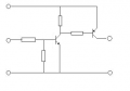
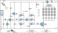
Problem : I need Improvement of this circuit because the white LED is not at full brightness when pulse coming from spark plug wire.

And i have try attach pickup coil as the sensor and hit a screwdriver to the pickup coil contact point and the LED is blink at full brightness. At this point i think to weak signal from wrapped copper wire.

Please can anyone help to improve this circuit. Thanks
 

Attachments

#12

Joined Nov 30, 2010
18,224
It used to work. It doesn't work right now. Replace parts until it gets better like when it was new. No need to redesign something that works when it is not broken.
 

Thread Starter

inogbox

Joined May 12, 2012
8
It used to work. It doesn't work right now. Replace parts until it gets better like when it was new. No need to redesign something that works when it is not broken.
What do you mean "It doesn't work right now" ?, i'm build it on the breadboard.
 

#12

Joined Nov 30, 2010
18,224
Well, I completely misunderstood you.

This has been done many times before. google, "timing light schematic" and find many good examples. Pick one and we can polish it for your purpose.
 

MrChips

Joined Oct 2, 2009
30,795
What is providing the 3V power?

I would go with 12VDC from the battery. Use a current limiting resistor.
And I would try a MOSFET, something like 2N7000, with appropriate gate protection.
 

Thread Starter

inogbox

Joined May 12, 2012
8
Well, I completely misunderstood you.
it's okay :).

What is providing the 3V power?...
2 cell 1.5v battery
....
And I would try a MOSFET, something like 2N7000, with appropriate gate protection.
In my place i live hard to find electronic component and i just learn electronic. Can this archived using basic components. What about add one more transistor and using capacitor to trigger second transistor to connect ground.
 
Last edited:

#12

Joined Nov 30, 2010
18,224
The first apparent mistake is that a white LED can be fired with 3 volts. Most of them will not work at that voltage. Second, when you provide the excess voltage, you need a resistor to limit the current through the LED. Third, most timing lights use a xenon flash tube because you need a lot of light, most of the time. If you want to do this with an LED, you need: a pickup, a way to convert that voltage pulse to current, and enough power to run the LED. I'm thinking a 2N7000 mosfet, 12 volts, and 470 ohms. Lots of current amplification and a limiting resistor for the excess voltage. You also need to protect the mosfet with perhaps a zener diode from gate to source so the pickup pulses can not blow its gate out.

One of my circuits for more gain and nothing exotic is what I call a double invert circuit:
Somebody else called it a Sziklai pair, but I didn't hear about that until I had been using MY invention for 40 years.
 

Attachments

Last edited:

Thread Starter

inogbox

Joined May 12, 2012
8
.....current, and enough power to run the LED. I'm thinking a 2N7000 mosfet, 12 volts, and 470 ohms. Lots of current amplification and a limiting resistor for the excess voltage. You also need to protect the mosfet with perhaps a zener diode from gate to source so the pickup pulses can not blow its gate out.....
I found on the web, do you mean like this circuit?

if this circuit that you mean, i will try find 2N7000 mofset later morning , now is 3.40 AM in my place. Then i try to build it and tested. I will report soon the result. thank you ;)
 

Attachments

#12

Joined Nov 30, 2010
18,224
That's what I was thinking.
The 1N400x probably is not necessary because a zener diode run backwards is a simple diode, and the size of C1 depends on how much coil you have. You might have to experiment with that.

PS, the only reason that LED can survive with only 10 ohms to protect it is that it only flashes for a very short time. If you try to stretch the time out, it will smoke.
 
Last edited:

Thread Starter

inogbox

Joined May 12, 2012
8
I stopped this project temporary. Because i cannot get 2N7000 mosfet, i try to replace that using K3296 from old computer motherboard but still cannot get the LED blinking. Because from K3296 datasheet description it's for low voltage and high current application, in my case the pickup coil just produce 0.5v measured using AC scale on analog multimeter and i think the current is very low compared from my second attempt when the second pickup coil i hit using screwdriver. like :
.......If you want to do this with an LED, you need: a pickup, a way to convert that voltage pulse to current, and enough power to run the LED.....
So if anyone who interesting build timinglight.from other site .jpg circuit, this is was original page http://www.howtoalmanac.com/kevin/projects/automotive/timinglight.htm

And i still open for suggestion to build this project :rolleyes:
 

#12

Joined Nov 30, 2010
18,224
More likely the problem is, "a few feet of wire for the pickup"...your cheap, hand made coil with nowhere near enough turns. If it can't produce more than 1/2 of a volt, it can't turn on a transistor. A mosfet needs at least 4 or 5 times that much voltage. (Pretty much no current, but several volts.) Back up, start over, and make a coil that actually works.

My personal cheat was to get a model number from a Sears timing light and buy the pickup coil as a repair part. Ten bucks instead of a hundred, and I have a scope adapter for car engines!
 

solac

Joined Aug 13, 2015
18
I actually tried this circuit and can't get it to work. I tried to follow how the pick up coil was made in his YouTube demo from this site only I find it very difficult to turn 500 turns of 30 awg wire on the modified transformer coil. So I stopped at around 300 give or take a few. So when I tried it on my car the led was not very bright and the led started blinking as soon as I connected the negative side of the circuit to the battery. The pick up inductor I made was already picking up static about a feet away from the distributor. I flashed the light at the timing mark and couldn't see the timing mark. Was wondering if this would only work for a scooter or a single cylinder engine or my inductive pick up wasn't correct? I found another similar schematic of this which used 1.8k resistor on the gate of 2n7000 and just 13 turns of wire on the spark plug as pick up. I haven't tried it though. Since I figured the brightness of the led would probably be the same. So weak, at total darkness I still had a hard time seeing anything
 
Last edited:

solac

Joined Aug 13, 2015
18
The light is so weak I could barely see the crank pulley. With a commercial timing light that I borrowed I can see the timing mark no problem. Plus the fact that the the led starts blinking even if the pick up is no where near no. 1 spark plug cable. Where is it getting the pulse?. If move the pick up away from the engine the light stops blinking. IL try to upload photos of the pick up that I made.
 

#12

Joined Nov 30, 2010
18,224
I suggest a volume control between the coil/capacitor combination and the rest of the circuit to reduce sensitivity. As for the LED being dim,
most timing lights use a xenon flash tube because you need a lot of light
 

solac

Joined Aug 13, 2015
18
mmm, i don't really understand how electronic stuff works. i just know a little bout electronics. :)
how do i add a volume control ? is that a potentiometer ? yeah i do know, it wont be as bright as a xenon flash tube. but i was hoping a kind of flash light brightness atleast. its not even as bright as a flash light as i could barely see the pulley in darkness. there might be something wrong with my build? i was thinking of adding some more leds like the other circuit had 4 leds. by the way when i testing this thing it burned the led and i think the transistor is fried as well.


Attachments

Last edited:

solac

Joined Aug 13, 2015
18
Don't get me wrong. I'm not looking to getting a flash as bright as the xenon flash. I just want it to work that's all.

Anyway thanks for your help
 
Top