help please (Charging LiPo Solar, for LED light for Mailbox)

Thread Starter

Guest3123

Joined Oct 28, 2014
404
I want to charge a LiPo battery via the ballance plugs. So it's a ballanced charge, and I don't run into any problems, day in and day out.
The light can be very small, but I want it to be bright. So even using a couple LEDs would make a really nice and bright mailbox light.
I want the light to last all night long. So that means I need to know the current draw of the LEDs to the capacity of the LiPo batteries.
etc.
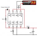
I need help on this. I need help with the fact how to use an Op Amp to shut the light off when it's daylight out.. or a specific amount of light is sensed.

Light Sensed : Start charging, and turn off the LED lights.
Light Sensed : Set the Op Amp to detect 4.2vdc. When it does, shut down the charging, &
LED's stay off until darkness is detected.

That's my idea of a mailbox light, with very long battery life, and high current solar charging abilities.

Can anyone help me with this kind of circuit?
 

wayneh

Joined Sep 9, 2010
17,496
So basically you want a beefed up solar landscape light. More LEDs, a bigger battery, and a bigger panel to power it all. Such things are available ready-made in the hardware store. Just sayin'.

You'll want a better charging strategy than a voltage cutoff. Head over to battery university for details. Or find an IC (from TI, for instance) that is designed for your battery chemistry. This will ensure a long life for the battery. There's a reason all those cheap solar lights use Nicad batteries - it's because they are the easiest to charge with a small solar cell. They can tolerate the continuous charge current from the panel and won't be damaged by an overcharge. Other chemistries are not so robust. Lead acid is the next easiest.

There are several ways to detect low light. Many solar lights use a CdS cell but lately I've been seeing the cheapest ones getting by without it. They just use the panel as the detector. Again, as with battery charge ICs there are purpose-built ICs designed to run solar lights, and some may even include the battery tending functions. You may want to investigate those rather than trying to design your own.
 

Thread Starter

Guest3123

Joined Oct 28, 2014
404
So basically you want a beefed up solar landscape light. More LEDs, a bigger battery, and a bigger panel to power it all. Such things are available ready-made in the hardware store. Just sayin'.

You'll want a better charging strategy than a voltage cutoff. Head over to battery university for details. Or find an IC (from TI, for instance) that is designed for your battery chemistry. This will ensure a long life for the battery. There's a reason all those cheap solar lights use Nicad batteries - it's because they are the easiest to charge with a small solar cell. They can tolerate the continuous charge current from the panel and won't be damaged by an overcharge. Other chemistries are not so robust. Lead acid is the next easiest.

There are several ways to detect low light. Many solar lights use a CdS cell but lately I've been seeing the cheapest ones getting by without it. They just use the panel as the detector. Again, as with battery charge ICs there are purpose-built ICs designed to run solar lights, and some may even include the battery tending functions. You may want to investigate those rather than trying to design your own.
Ok. I know how to do it, I'm just being lazy. Thanks for the support. There's an IC that's called the MAX1811 from Maximum Integrated.

I'll get around to drawing the circuit, including the part where it turns off during the day, or when it senses a certain amount of sunlight, and switches back to charging. 500mA is too low though. SHTF senario. I want it to charge in minutes. This isn't just for a mailbox light. It's a learning experience.

I'm aware I could just use a Solar Panel, or make my own from eBay. 0.5 Vmax, something like 3.6 Imax from these.
Alright, so even if I didn't want to build them, then this is expensive, for 5V @ 1A.

So it's PV > PWM or MPPT Charge Controller > Battery & DC Load. etc.

That's just DC. Not talking about hooking the batteries to the Inverted.

solar-components.jpg


It's VERY EASY to use the solar panel with charge controller.

Anyways, I'll draw up a circuit latter. I'm just way too busy to do it right now.
 

Thread Starter

Guest3123

Joined Oct 28, 2014
404
Alright, so this is the circuit I found on that video.

ScreenHunter_08 Jan. 09 14.37.jpg ScreenHunter_09 Jan. 09 14.37.jpg
ScreenHunter_09 Jan. 09 14.41.jpg
It's 6.5V, 7.2A, because the voltage needs to account for the voltage drop of the diode. The current on the other hand.. Idk how to handle it. The solar cells are going to output 7.2A MAX. How do I bring it down?

I also have been learning about the LM317 and the LM338 to regulate a constant current. The LM317 and LM338 can also be used to regulate the voltage. But shouldn't need to worry about the voltage, because the MAX1811 IC, to regulate the voltage, and make sure the battery is charging, not charging when full, etc.
 

Attachments

Last edited:

wayneh

Joined Sep 9, 2010
17,496
That IC can supply only 0.5A max current. Why use a solar panel that supplies 14X that?

But anyway, as long as the panel's max voltage is below 7V so that is doesn't damage the IC, the IC will control the current to the battery no matter how much current the panel is capable of. You don't have to do anything else.
 

Thread Starter

Guest3123

Joined Oct 28, 2014
404
I don't like using crap that's already built. I'm still pretty new to electronics, but I have a good feeling about electronics, and making simple stuff. This circuit is pretty big, but it's pretty simple stuff.

I was looking at the LM318/LM338, Specified 5A Output Current

That's what I really want to work with.. Just the ICs, then I can choose whatever voltage I want and everything.

These modules aren't helping me.. I even found a TP4056 on ebay.

With a pathetic 1A output. That's lame.

I want to supply my own voltage, and my own current, and I want to check the battery myself, I don't want a module or whatever doing it for me. That's lame, and child's play.

I want to work with real components. A 12 year old can go online or to the hardware store and buy this crap. I just basically came here to get a little help, which I can say your trying to help me, thank you.

I like the LM318 or LM338. I like the fact that I can supply my own current.
I also like the Op-Amp, and n-Channel Mosfets. So I can check the battery myself with a my own reference voltage, etc, and protect my own stuff using the components I've hand picked.

I'll just keep watching these videos and let's see what I come up with in as my circuit drawing in a couple days.
 

Attachments

Last edited:

wayneh

Joined Sep 9, 2010
17,496
How is it possible that the IC will stop the 7.2A coming off the panels?
The load determines the current, not the source. When you plug a 60W lamp into your wall, it draws about 1/2A, not the 15A that the circuit could supply without blowing your breaker, nor the megawatts the power company can produce. Same deal with the panel.

The reason you sometimes dump current into a dummy load is to regulate voltage down to some acceptable level. As long as your panel voltage won't fry the IC, you don't need to draw it down by diverting current.
 

Thread Starter

Guest3123

Joined Oct 28, 2014
404
The load determines the current, not the source. When you plug a 60W lamp into your wall, it draws about 1/2A, not the 15A that the circuit could supply without blowing your breaker, nor the megawatts the power company can produce. Same deal with the panel.

The reason you sometimes dump current into a dummy load is to regulate voltage down to some acceptable level. As long as your panel voltage won't fry the IC, you don't need to draw it down by diverting current.

So regardless if I have 10A coming from the panels, the little IC can handle it? wtf..? Must be a mosfet or something protecting it.
That's what I thought anyways.

Ok, well I don't really understand how that's possible without a mosfet protecting it..

I built a couple box mods, and I have to protect my switch using an n-Channel MOSFET. I've worked with n-Channel MOSFETs and I honestly think they are the world when it comes to protecting sensitive electronics..

I just remember hearing about the current that comes off some of these panels is retarded. I mean were talking several tens of amps on some systems @ 24Vdc.

Anyways.. I changed my reply.. what seems after you replied.

I don't like using crap that's already built. I'm still pretty new to electronics, but I have a good feeling about electronics, and making simple stuff. This circuit is pretty big, but it's pretty simple stuff.

I was looking at the LM318/LM338, Specified 5A Output Current

That's what I really want to work with.. Just the ICs, then I can choose whatever voltage I want and everything.

These modules aren't helping me.. I even found a TP4056 on ebay.

With a pathetic 1A output. That's lame.

I want to supply my own voltage, and my own current, and I want to check the battery myself, I don't want a module or whatever doing it for me. That's lame, and child's play.

I want to work with real components. A 12 year old can go online or to the hardware store and buy this crap. I just basically came here to get a little help, which I can say your trying to help me, thank you.

I like the LM318 or LM338. I like the fact that I can supply my own current.
I also like the Op-Amp, and n-Channel Mosfets. So I can check the battery myself with a my own reference voltage, etc, and protect my own stuff using the components I've hand picked.

I'll just keep watching these videos and let's see what I come up with in as my circuit drawing in a couple days.
 

wayneh

Joined Sep 9, 2010
17,496
I want to supply my own voltage, and my own current, and I want to check the battery myself, I don't want a module or whatever doing it for me.
I get that, but unfortunately some battery chemistries are not that simple. With lead acid you can charge to a constant voltage. With Nicad you can charge at a constant current forever because the nicads can tolerate that. But other chemistries cannot tolerate constant current trickle - they will overcharge and be destroyed. And you cannot measure state-of-charge simply by voltage. That IC handles all those problems AND can use a wide range of input voltage. It'd be really tough to roll your own to come anywhere near. If you don't like the particular Maxim IC, look at similar ICs from TI and Linear. They all offer a range of battery-tending ICs, and some are specifically designed for a solar panel source.

Or, use a sealed lead acid (SLA) battery.
 

wayneh

Joined Sep 9, 2010
17,496
So regardless if I have 10A coming from the panels, the little IC can handle it? wtf..?
The little IC ensures that there is NOT 10A coming from the panel. You would have to place a short across the poles of the panel to draw that maximum current. The little IC is not a short, it's a 1/2A load just like a 60W lamp in your house.
 

Thread Starter

Guest3123

Joined Oct 28, 2014
404
The little IC ensures that there is NOT 10A coming from the panel. You would have to place a short across the poles of the panel to draw that maximum current. The little IC is not a short, it's a 1/2A load just like a 60W lamp in your house.
Ok. That's a great reply, thanks.

I might know Ohm's law, and know a little about n-Channel mosfets, and even how to make a logic NAND gate with n-Channel mosfets, but it seems I still have a little learning to do about what seems like basic electricity laws.. idk.

Maybe I've missed something here.

Ok, so the panels are not forcing and outputting 10A or 7.2A in my case.
They are supplying current.

Just because a wall wart 5V 1A PS says on the output specs on the sticker, doesn't mean it's outputting 1A @ 5V.

I learned that quite some time ago..

What I seem to be confused about is the panels ARE NOT pushing 7.2A threw the little IC.
If that's it, then I'm half way done with my project. If not, I'm in some pretty big trouble.

How the hell.. excuses the language.. But.. how the heck do I FORCE current and FORCE voltage onto something?

So if I had something like this..
ScreenHunter_09 Jan. 09 22.04.jpg

So that means the device is charging at 5V @ 0.5A.. ? Correct?

Despite what I've talked about before, about the LM317, etc. Does this force 0.5A @ 5V onto the device, in this case it's a smartphone..?
 

wayneh

Joined Sep 9, 2010
17,496
So that means the device is charging at 5V @ 0.5A.. ? Correct?

Despite what I've talked about before, about the LM317, etc. Does this force 0.5A @ 5V onto the device, in this case it's a smartphone..?
No, the current to the phone is controlled only by whatever is inside the phone, a black box. In your diagram the resistor passes a current of 0.5A but the phone current is unpredictable. The resistor is predictable because it's a passive component designed to be predictable.
 

Thread Starter

Guest3123

Joined Oct 28, 2014
404
No, the current to the phone is controlled only by whatever is inside the phone, a black box. In your diagram the resistor passes a current of 0.5A but the phone current is unpredictable. The resistor is predictable because it's a passive component designed to be predictable.
So that also mean not this too..

Despite not using a diode.. either with mosfet, or regular diode.

ScreenHunter_10 Jan. 09 22.32.jpg


bench top power supplies can force current into things. I've seen test videos on silicoln wire vs PTFE insulated wire, and it is POSSIBLE... Regardless if the smartphone or whatever wants it or not..

I also know that I know how to do it already, with LEDs.

In order to make an LED light, you must know a little about OHMs law.

Subtract the LEDs Forward Voltage from the supply voltage.
(Yes, this is to do with the mailbox light)
6.5V - 2.2Vf = 4.3 volts needs to be dropped.. Let's use a resistor.
Also.. The LED needs only 20mA, or 0.02A.

So using Ohm's Law.. we can do that.

4.3V dropped / 0.02A = 215Ω resistor.

That give the LED 2.2V, and supplies a safe 0.02A of current to the LED.

Now.. Is it that simple for charging a smartphone or let's keep it simple, and let's say a rechargeable battery?

So let's say I wanted to supply 5V @ 1A..

So my supply voltage from the solar panel array is 6.5V.
and the panels can supply up to 7.2A.

6.5V - 5V = 1.5V to be dropped.
1.5V / 1A = 1.5Ω

So my circuit needs a 1.5Ω resistor. maybe even put in a diode.

So the voltage is gonna drop after the diode, so I need to calculate the
resistor value based on the voltage after the diode..

Is that correct?
 
Last edited:

wayneh

Joined Sep 9, 2010
17,496
Yes, although that is a little more predictable and is actually the cheapest and simple battery charger. It limits the maximum current (when the battery is at zero volts) to 0.5A and it goes down towards zero as the voltage approaches 5V.
 

Thread Starter

Guest3123

Joined Oct 28, 2014
404
Yes, although that is a little more predictable and is actually the cheapest and simple battery charger. It limits the maximum current (when the battery is at zero volts) to 0.5A and it goes down towards zero as the voltage approaches 5V.
I'm really sorry, Idk why I do that, but can you also look at what I've added to the post.. please.

I always do that.. I post it, and then go back sometimes like 2, or even 3 or more times.. lol..

Yeah.. kinda figured I was on the right track..

I also know that I know how to do it already, with LEDs.

In order to make an LED light, you must know a little about OHMs law.

Subtract the LEDs Forward Voltage from the supply voltage.
(Yes, this is to do with the mailbox light)
6.5V - 2.2Vf = 4.3 volts needs to be dropped.. Let's use a resistor.
Also.. The LED needs only 20mA, or 0.02A.

So using Ohm's Law.. we can do that.

4.3V dropped / 0.02A = 215Ω resistor.

That give the LED 2.2V, and supplies a safe 0.02A of current to the LED.

Now.. Is it that simple for charging a smartphone or let's keep it simple, and let's say a rechargeable battery?

So let's say I wanted to supply 5V @ 1A..

So my supply voltage from the solar panel array is 6.5V.
and the panels can supply up to 7.2A.

6.5V - 5V = 1.5V to be dropped.
1.5V / 1A = 1.5Ω

So my circuit needs a 1.5Ω resistor. maybe even put in a diode.

So the voltage is gonna drop after the diode, so I need to calculate the
resistor value based on the voltage after the diode..

Is that correct?
 

wayneh

Joined Sep 9, 2010
17,496
That works when the load current is constant and predictable like an LED. In that case a simple resistor drops voltage as you've shown. But some devices like cellphones expect a constant voltage no matter what current they draw.
 

Thread Starter

Guest3123

Joined Oct 28, 2014
404
That works when the load current is constant and predictable like an LED. In that case a simple resistor drops voltage as you've shown. But some devices like cellphones expect a constant voltage no matter what current they draw.
Good. I like the fact that the cellphone wants a constant voltage, etc. I'll work on it.

And to supply a constant voltage no matter what, I use a L7805 voltage regulator.
To supply a constant current I use a LM318/LM338,, or for smaller current LM317.

So how the heck can I get these two components to work together, and give my battery a constant current and constant voltage no matter what the load, and no matter what the supply voltage.. sorta...?

I'll go and see what I can do.. As far as messing with this type of circuit.. with those two components.

This is gonna take a little time.. I might not get back till tomorrow.. Thanks for the help so far.


ALSO.. I'm paying closer attention to the LM805 linear voltage regulator IC.

So heat is generated, when I want to use this to regulate the voltage output.

(Vin - Vout) x Iout

So 6.5V - 5V = 1.5 x 1A = 1.5 Watts of heat. (MAX output current)

Also, I'll have to add two more cells to the solar array.. So now it's 7V.

Because of the LM7805's dropout voltage range. which is 2V.

7V - 5V = 2V x 1A = 2 Watts of heat.

Also.. if I did do 7V, then the output voltage might drop slightly, which is fine.. I only need MAX of 4.2V I think to charge the battery. Even if it were 4.6V, that's fine I think.
 
Last edited:

Thread Starter

Guest3123

Joined Oct 28, 2014
404
You can't!

LM2940, 1A output, 0.5A Dropout voltage.

So now I can use a lower supply voltage. Let's say 6V

So that's 6V - 5V = 1V x 1A = 1 Watt of heat dissipated.

But basically, I just contradicted myself. I want to shoot for more current to charge the LiPo or whatever faster in case I don't get much or if I get very little sunlight that day..

I just drew this up.. but I don't think it's any good.

The mosfet is protecting the output pin on the LM7805.
The 5Ω resistor is supposed to give the battery 1A of current.

But it's not.. 5V - 5V = 0V / 1A = 0...

The voltage coming into the resistor before the battery or in this case, the load, needs to be higher.

Or.. Supply voltage 5v - 4.5V = 0.5V / 1A = 4.5Ω

Does that work? It's a constant voltage supply with constant current.

ScreenHunter_10 Jan. 09 23.50.jpg
 

Thread Starter

Guest3123

Joined Oct 28, 2014
404
lol.. that resistor actually needs to be something like 0.5Ω

We calculate the power dissipated on the resistor by the amount of voltage that is being dropped accross the resistor.

5Vout - 4.5 desired voltage = 0.5v to be dropped accross the resistor.
0.5v / 1A = 0.5Ω Resistor.

Ohm's Law, let's find the power dissipated by the resistor.

0.5V x 0.5V = 0.25V / 0.5Ω = 0.5 Watts. Not too bad.

So is that a little better, or no..?

I know.. what's the sense of having the mosfet, if it's just going to draw the same amount of current.. right?

So let's do 5V - 4.5 = 0.5V / 3A = 0.2Ω
0.5V x 0.5V = 0.25V / 0.2Ω = 1.25 Watts..

Getting a resistor like that is possible on Mouser Electronics. I checked.

ScreenHunter_10 Jan. 10 00.17.jpg

It seems it's just not possible to protect the IC while also using the voltage from it.
 
Last edited:
Top