help on simple power supply using circuit wizard

Thread Starter

Johnson Andres Gangob

Joined Jan 24, 2019
4
good day

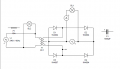
i'm new in using circuit wizard and i'm having a hard time setting up a simple power supply, especially on the transformer windings. I can't get a 3 amps 24v during simulation.

given:
transformer:
primary: 240v 1amps
secondary:24v 3 amps
 

Attachments

ericgibbs

Joined Jan 29, 2010
18,766
hi JAG,
Welcome to AAC.
I do not use Circuit Wizard, but where are you measuring the Vdc output from the bridge rectifier, also where is the smoothing capacitor.?
Mark it on your diagram.
E
 

Thread Starter

Johnson Andres Gangob

Joined Jan 24, 2019
4
thank you, here is the updated diagram. i measure the vdc and i got 23v, however, i only get 100mA using an altimeter. in addition, when i replace the voltmeter on the circuit wizard with an filter capacitor 1000micro farad 100v and put an fuse, all components explode
 

Attachments

jayanthd

Joined Jul 4, 2015
945
thank you, here is the updated diagram. i measure the vdc and i got 23v, however, i only get 100mA using an altimeter. in addition, when i replace the voltmeter on the circuit wizard with an filter capacitor 1000micro farad 100v and put an fuse, all components explode
There is no load resistor and ground connection in bridge rectifier circuit.
 
Last edited:

Thread Starter

Johnson Andres Gangob

Joined Jan 24, 2019
4
where should i put it and what should be the value.
btw can you recomendme a free electronic offline simulator other than circuit wizard, it seems i cant change the transformers output current
 

jayanthd

Joined Jul 4, 2015
945
where should i put it and what should be the value.
btw can you recomendme a free electronic offline simulator other than circuit wizard, it seems i cant change the transformers output current
What load current you want ? See attached video.

Extract the .rar file using WinRaR 5.x and view the .wmv video file in Windows Media Player or VLC Player.

AC mains voltage = 240V rms 50 Hz
Trf ratio is 10:1 step-down
Secondary voltage is 24V AC rms
DC output voltage across load = (24V * 1.4142) - 1.4 [2 X 0.7, (0.7 = 1 diode drop] = 33.9408 - 1.4 = 32.5408V DC.

You cannot change transformer current without changing the load resistor.

Vpri/Vsec = Npri/Nsec = Isec/Ipri

Set RL in my circuit to get the required secondary and primary currents.

I don;t know about any free offline electronic circuit simulator. I have licensed version of Proteus. I don't use Circuit Wizard much.


CktWiz_2019-01-27_00-36-30.png
 

Attachments

Last edited:

jayanthd

Joined Jul 4, 2015
945
Primary currents depends upon the secondary current and secondary current depends upon load RL here.

Vpri/Vsec = Isec/Ipri = Npri/Nec

240/24 = 10 is not equal to 3A/1A = 3 but 240/24 = 10 = 10:1 ratio that is Npri/Nsec = 10/1; 10 turns of primary = 1 turns of secondary.

If you want Isec = 3A rms then

Ipri = Isec / (Vpri/Vsec) = 3A/(240V/24V) = 3A/10V = 0.3A = 300mA.

Edit:

LaTeX

\({Ipri = Isec / (Vpri/Vsec) = 3A/(240V/24V) = 3A/10 = 0.3A = 300mA}\)
 
Last edited:

bertus

Joined Apr 5, 2008
22,270
Hello,

You made a mistake in your explanation:

Ipri = Isec / (Vpri/Vsec) = 3A/(240V/24V) = 3A/10V = 0.3A = 300mA.

There can not be V at the given point.

Ipri = Isec / (Vpri/Vsec) = 3A/(240V/24V) = 3A/10 = 0.3A = 300mA.

Bertus
 

jayanthd

Joined Jul 4, 2015
945
AC mains voltage = 240V rms 50 Hz
Trf ratio is 10:1 step-down
Secondary voltage is 24V AC rms
DC output voltage across load = ((24V * 1.4142) - 1.4) [1.4 = 2 X 0.7, (0.7 = 1 diode drop] = (33.9408V - 1.4) = 32.5408V DC.

Ipri = Isec / (Vpri/Vsec) = 3A/(240V/24V) = 3A/10 = 0.3A = 300mA.

In image RL (Load Resistance) = 10k and IL (Load Current) = 3.22mA

IL = Vdc/RL = 32.5408/10k = 3.25408mA (approx same as in simulation (image)).


CktWiz_2019-01-27_00-36-30.png
 
Top