Facebook
 Google
 GitHub
 Linkedin
Hi everyone!
I'm trying to solve a problem i have, and i must warn in advance that i am very new to circuits.
So i'm seeking help and advice for my case and i need it layed down on me in a way simple to understand.
Thank you for your patience in advanced.
So here it goes:
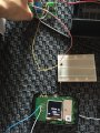
I am building a box to put my wifi hotspot away in the car. So all i want to do is to push the button and both the usb charging and the hotspot turn on. All is setup up but the quirk is that i have to figure out on how to make the switch 12v led only when the hotspot is on.
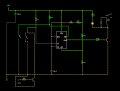
My hotspot only has one push button that you have to press for a few moments to turn on and off, and i detected that it grounds about 1,8v when you press it. And no led light is there to say that it is on, unless the display that goes off to power save mode after a while. The board itself only has 2 test pads that i found to be 1,8v when its working, so i guess its the only place i can "connect" the device to power the switch led. I tried one 4n25 , placing the anode and cathode to the hotspot 1,8v and the colector and emitter conected to the start switch from a 12v start/stop timer from velleman (model k2579).
It didn't work.
The voltage droped to 0,9v and i measured the current between the hotspot testpad and the 4n25 and it was about 8uA (im not sure about the precision of the reading now but it seemed to me that it was way to low to be possible)
I use this timer that i had here only for driving the relay that feeds 12v to the switch led.
The start trigger switch also grounds 12v when pressed.
After that i decided to test some bc547 npn transistor that i had also laying around.
I connected the base to the +1,8v and the colector to the +12v from the timer and emitter to the timer's ground.
Didn't work.
Where am i failing in concept? Should'nt i be able to drive the timer trough some transistor? Any better ideas?
I don't know how to measure the current from my hotspot on the test pads to know where the problem may be.
Should i connect both grounds? ( hotspot battery voltage is rated for 3,8v)
Thank you for your help and time
I'm trying to solve a problem i have, and i must warn in advance that i am very new to circuits.
So i'm seeking help and advice for my case and i need it layed down on me in a way simple to understand.
Thank you for your patience in advanced.
So here it goes:
I am building a box to put my wifi hotspot away in the car. So all i want to do is to push the button and both the usb charging and the hotspot turn on. All is setup up but the quirk is that i have to figure out on how to make the switch 12v led only when the hotspot is on.
My hotspot only has one push button that you have to press for a few moments to turn on and off, and i detected that it grounds about 1,8v when you press it. And no led light is there to say that it is on, unless the display that goes off to power save mode after a while. The board itself only has 2 test pads that i found to be 1,8v when its working, so i guess its the only place i can "connect" the device to power the switch led. I tried one 4n25 , placing the anode and cathode to the hotspot 1,8v and the colector and emitter conected to the start switch from a 12v start/stop timer from velleman (model k2579).
It didn't work.
The voltage droped to 0,9v and i measured the current between the hotspot testpad and the 4n25 and it was about 8uA (im not sure about the precision of the reading now but it seemed to me that it was way to low to be possible)
I use this timer that i had here only for driving the relay that feeds 12v to the switch led.
The start trigger switch also grounds 12v when pressed.
After that i decided to test some bc547 npn transistor that i had also laying around.
I connected the base to the +1,8v and the colector to the +12v from the timer and emitter to the timer's ground.
Didn't work.
Where am i failing in concept? Should'nt i be able to drive the timer trough some transistor? Any better ideas?
I don't know how to measure the current from my hotspot on the test pads to know where the problem may be.
Should i connect both grounds? ( hotspot battery voltage is rated for 3,8v)
Thank you for your help and time