Help Needed: Designing a Long On/Off delay timer for controlling a relay

Thread Starter

pogo44

Joined May 25, 2024
6
Hi everyone,

I'm working on my first ever circuit and PCB board for an automatic watering project that requires a long on/off time delay relay controller. I could really use some guidance from this knowledgeable community.

Project Overview:

  • Objective: To design an on/off timer circuit that can manage long on/off time delays.
  • Requirements:
    • On Time: Separately adjustable from the off time. Currently, I'm planning to set a frequency and use a binary ripple counter (CD4060) to divide it, effectively making the frequency much lower.
    • Off Time: Same approach as ON time.
    • Load: Capable of switching various voltages/currents. The relay will likely support 12V or the electric grid (230V in my case).
    • Accuracy: High accuracy isn't crucial, but I would like it to be repeatable. For instance, if I want an off delay of about 12 hours, I can set the approximate frequency required and select the correct output on the counter to divide it accordingly. A slight deviation of a few minutes is acceptable.
    • Interface: I plan to use an Excel sheet with pre-calculated capacitor/resistor values for certain frequencies. Would it be beneficial to use a potentiometer on the frequency circuit for fine adjustment?
Challenges I'm Facing:

  • Parts on Hand: I want to use the components I already have: NE555P, CD4060, 1/4W and 1/8W resistors, ceramic capacitors, transistors, etc. (I'll attach a photo of the labels on my component drawer. I have these parts because I enjoy fixing circuits with obviously broken/burned components.)
  • Avoiding Microcontrollers: I'd like to make this circuit without any microcontrollers, even though I know it would have been faster and easier.
  • Inexperience with Components: I have not used transistors or counters before, so I'm unsure if my current design would work. I haven't added any resistors to the transistors yet, but I know they are needed and plan to do so.
  • Resetting the Counter: I assume that directly connecting the output of my counter to itself to reset its count might cause issues and uncertainty. How would you go about fixing this? Should I use some sort of delay or an additional IC?
Any suggestions, schematics, or references to similar projects would be greatly appreciated. Thank you in advance for your help!

I know I haven't explained everything in detail, but I plan to make a follow-up comment with my thought process behind each part of the circuitry so you can understand what I'm trying to achieve.

Best regards,

Nik


Screenshot_20240525_195317.png


Screenshot_20240525_195447.png

1716659801857.jpg
 

Thread Starter

pogo44

Joined May 25, 2024
6
I know it's irrational to go with this option instead of an MCU, saving money and time. But, I really want something more retro looking. I am planning on using MCUs in the future, but before I delve into that, I want to get some experience designing PCBs and circuits (more parts on board to practice space management and placing traces).


TL;DR: I'm working on a retro-style timer circuit using the CD4060 and NE555P. The CD4060 sets a frequency and divides it, with an output triggering and resetting the NE555. I need to ensure proper pull-down resistors and transistor interfaces to avoid false triggering and ensure reliable operation. Seeking advice on setup and improvements.


Detailed Circuit Information:

Part 1: CD4060 Configuration


1716665099236.png

I'm using the CD4060 with the built-in oscillator to preset a frequency based on the amount of time I want the circuit to output the ON/OFF signal. The frequency is set with the RC part, and it requires a second resistor for reasons I haven't really looked into yet.

Once the frequency is set, it goes through the binary counter where I can divide it by choosing an output pin using the switch.

  • Issue: I directly connected the Qn output to the CLR pin to reset the count. I think I still need to add a pull-down resistor to prevent false triggering of the reset pin. Is this correct?
  • Uncertainty: I don't know whether the output Qn can even trigger its own CLR pin. In addition to triggering the clearing of the count, I want to use this momentary signal to trigger the NE555P in bistable mode to turn on its output with the help of a transistor.
  • Doubt: How could a logic signal possibly trigger a transistor? Should I be using an op-amp?


Part 2: Triggering the NE555

1716665136157.png

In this part, I'm trying to use the previously mentioned counter signal to pull the TR pin on the 555 low to trigger it. I'll ignore what this does to the ON part of the circuit until later on in the post.

  • AND Logic: Because I'm using the same signal that triggers the 555 to clear the counter, the AND circuit works as intended and only recognizes the 555 signal for now.
  • Cycle: After another cycle, we should get another signal from the counter, which should trigger the other transistor in the AND logic, sending a reset signal to the 555 timer.

Part 3: Tandem NE555 Timers
1716665743002.png

For the tandem part of the 555, once one of the 555s is triggered when the circuit is turned on while one of the physical buttons is held:

  • Output: The output turns on, sending power to the other 555 reset pin transistor and should be disabled for the duration of the first 555's cycle.


Summary and Key Points:

  • Pull-Down Resistor: Add a pull-down resistor to the CLR pin of the CD4060 to prevent false resets.
  • Transistor Interface: Use transistors to interface the CD4060 outputs with the NE555 timer’s TR and RST pins for reliable operation.
  • Debouncing and Filtering: Use capacitors to filter any noise from the CD4060 outputs before they trigger the NE555 timers.
I appreciate any feedback on whether this approach is correct and if there are any improvements I can make. Thanks!
 

MrChips

Joined Oct 2, 2009
31,172
I don't want to discourage you but this project is very ambitious for someone at your level of knowledge and experience.

Let us begin with some mundane schematic drawing errors.

1) Your schematic shows GND nodes and Vss nodes. Do you realize that these two are the same in this particular example? (They are not necessarily the same in all applications.)

2) For clarity, we tend to put VDD towards the top and GND or Vss towards the bottom.

3) Avoid having too many lines crossing. Instead, break the line and give it a netlist name.

4) Become familiar and learn to use decade units.
1000000Ω is written 1MΩ.
0.00000001F is written 10nF.

5) Select a part number for your transistors, e.g. 2N3904.

Now on to design flaws.

1) SW2 (SW_DIP_x10) shows 10 switches connecting to a single node. Generally, this is a no-no. You cannot connect two outputs together. This circuit would work only if your intention is to select only one output at a time.

2) You cannot drive the base of a transistor directly. You will destroy the transistor at the base-emitter junction. You need to insert a current-limiting series resistor such as 1kΩ.

3) Yes, you can drive a transistor from the output of a logic gate via a series resistor. You do not need an op amp.

4) You do not need to filter or debounce the output of logic gates.

5) Your 555-timer circuits are incorrect. THR (pin-6) and DIS (pin-7) are missing components. If you intend to use them as flip-flops, then use a flip-flop.

I would recommend that before you attempt this project, firstly learn how a transistor works and how to bias it properly.
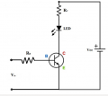
Start with something simple such as this circuit:

1716668045360.png

Learn the effects of the values of RB, Rc and Vcc on the brightness of the LED.
Try different colours of LEDs.
Try different input voltages Vis. Record at what input voltage Vis the LED turns on and turns off.

Next, try a simple 555-timer circuit flashing this same LED circuit at 1Hz.

You have to get your toes wet before you can learn to swim.
 

Ian0

Joined Aug 7, 2020
10,278
Instead of an ON-time and an OFF-time, have you considered an ON-time and a REPEAT-time?
That way the circuit that generates the repeat time can be an astable, and can trigger a monostable for the on-time.
Have you looked at the 4521 for really long times?
You can make a monostable out of the 4060, by connecting a Q output to the clock input via a diode. When the Q output goes high, it jams the oscillator to stop it running.
 

AnalogKid

Joined Aug 1, 2013
11,219

Thread Starter

pogo44

Joined May 25, 2024
6
I don't want to discourage you, but this project is very ambitious for someone at your level of knowledge and experience.

Let us begin with some mundane schematic drawing errors.

1) Your schematic shows GND nodes and Vss nodes. Do you realize that these two are the same in this particular example? (They are not necessarily the same in all applications.)

2) For clarity, we tend to put VDD towards the top and GND or Vss towards the bottom.

3) Avoid having too many lines crossing. Instead, break the line and give it a netlist name.

4) Become familiar and learn to use decade units.
1000000Ω is written 1MΩ.
0.00000001F is written 10nF.

5) Select a part number for your transistors, e.g. 2N3904.

Now on to design flaws.

1) SW2 (SW_DIP_x10) shows 10 switches connecting to a single node. Generally, this is a no-no. You cannot connect two outputs together. This circuit would work only if your intention is to select only one output at a time.

2) You cannot drive the base of a transistor directly. You will destroy the transistor at the base-emitter junction. You need to insert a current-limiting series resistor such as 1kΩ.

3) Yes, you can drive a transistor from the output of a logic gate via a series resistor. You do not need an op amp.

4) You do not need to filter or debounce the output of logic gates.

5) Your 555-timer circuits are incorrect. THR (pin-6) and DIS (pin-7) are missing components. If you intend to use them as flip-flops, then use a flip-flop.

I would recommend that before you attempt this project, firstly learn how a transistor works and how to bias it properly.
Start with something simple such as this circuit:

View attachment 323166

Learn the effects of the values of RB, Rc and Vcc on the brightness of the LED.
Try different colours of LEDs.
Try different input voltages Vis. Record at what input voltage Vis the LED turns on and turns off.

Next, try a simple 555-timer circuit flashing this same LED circuit at 1Hz.

You have to get your toes wet before you can learn to swim.

I cannot thank you enough for your detailed feedback! I appreciate the time and effort you took to point out the schematic errors and design flaws in my project. Your guidance is invaluable as I continue to learn and improve my skills. Here’s a structured reply addressing your points:


Thank you for your thorough feedback and guidance! I understand that this project is ambitious for my current level of knowledge and experience, and I appreciate your constructive criticism. Here are my thoughts and responses to your points:

Schematic Drawing Errors
  1. GND and Vss Nodes:
    I was aware that GND and Vss are the same in this example. I'll ensure to use consistent labeling in my schematics moving forward.
  2. Schematic Clarity:
    I'll follow the convention of placing VDD at the top and GND or Vss at the bottom for better clarity in my diagrams.
  3. Line Crossing:
    I'll avoid having too many lines crossing and instead use netlist names to make the schematic easier to read.
  4. Decade Units:
    Thank you for pointing that out. I'll make sure to use the proper notation like 1MΩ for 1000000Ω and 10nF for 0.00000001F in the future. (I only wrote it in this way because I was trying to get the simulation to work)
  5. Transistor Part Numbers:
    I’ll select specific part numbers for the transistors as-well as other components, to ensure clarity and precision in my design.
Design Flaws
  1. SW2 (SW_DIP_x10):
    I understand that connecting multiple outputs to a single node is generally a no-no. I intended for only one output to be selected at a time, but I'll reconsider the design to avoid potential issues.
  2. Driving Transistor Base:
    I'll include a current-limiting series resistor (like 1kΩ) to protect the transistor's base-emitter junction.
  3. Driving Transistor from Logic Gate:
    Thank you for clarifying that a series resistor is sufficient to drive a transistor from a logic gate output. I'll implement this in my design.
  4. Filtering/Debouncing Logic Gates:
    Noted. I won't worry about filtering or debouncing the output of logic gates.
  5. 555-Timer Circuits:
    I’ll revisit my 555-timer circuits and ensure that THR (pin-6) and DIS (pin-7) have the necessary components. If using them as flip-flops is inappropriate, I'll look into using actual flip-flop ICs.
Learning Recommendations
Your suggestion to start with a simple transistor circuit is well taken. I’ll begin by experimenting with:

  • Simple Transistor Circuit:
    I'll explore how different values of RB, Rc, and Vcc affect the brightness of an LED. I'll also try different LED colors and input voltages to understand the behavior better.
  • Simple 555-Timer Circuit:
    I'll create a basic 555-timer circuit to flash an LED at 1Hz, gaining hands-on experience with the component.
I’m committed to learning and improving. Thank you again for your invaluable advice, and I'll make sure to get my toes wet with simpler circuits before returning to this more complex project.
 

Thread Starter

pogo44

Joined May 25, 2024
6
Instead of an ON-time and an OFF-time, have you considered an ON-time and a REPEAT-time?
That way the circuit that generates the repeat time can be an astable, and can trigger a monostable for the on-time.
Have you looked at the 4521 for really long times?
You can make a monostable out of the 4060, by connecting a Q output to the clock input via a diode. When the Q output goes high, it jams the oscillator to stop it running.

Thank you for your insightful suggestions! I appreciate your alternative approach and will certainly consider it. Here are my thoughts on your points:

ON-Time and REPEAT-Time
I hadn't thought about using an ON-time and REPEAT-time approach, but it sounds like a more efficient method. Using an astable circuit to generate the repeat time and triggering a monostable for the ON-time seems like a great idea. This should simplify the timing control and make the circuit more reliable.

4521 for Long Times
I haven't looked into the 4521 IC, but I'll definitely research it for generating really long times. Its high division capabilities could be very useful for my application.

Monostable Configuration Using 4060
Your suggestion to make a monostable out of the 4060 by connecting a Q output to the clock input via a diode is intriguing. Stopping the oscillator when the Q output goes high to jam it is a clever technique to create a monostable circuit. I'll experiment with this configuration to see how well it fits my design needs.

Summary
  • ON-Time and REPEAT-Time: I'll explore this method, using an astable circuit for the repeat time and a monostable for the ON-time.
  • 4521 IC: I'll look into the 4521 for generating long time intervals.
  • Monostable 4060: I'll test the monostable configuration using the 4060 with a diode to jam the oscillator.

Thank you again for your suggestions.


Thank you for the suggestions! I appreciate the alternative approaches you mentioned. Here are my thoughts:

Lamp Timer
The BN-LINK Compact Outdoor Mechanical 24-Hour Programmable Dual Outlet Timer is certainly a practical and cost-effective solution. Its ability to be adjusted in 15-minute increments and allow for multiple on and off periods within 24 hours is very convenient. However, my goal with this project is to gain hands-on experience in designing and building circuits, which is why I'm looking to create a custom timer from scratch.

Programmable Timer Module
I see the value in using a programmable timer module from eBay, especially since they offer fine adjustments down to 1-second increments and are similarly priced. While these modules are highly functional and could simplify my project significantly, I am aiming to learn more about circuit design and PCB layout through this exercise.

Summary
Pre-made Solutions: Both the mechanical timer and the programmable timer module are excellent suggestions for practical applications and could save time and effort.
Learning Experience: My main goal is to develop my skills in circuit design and PCB layout, which is why I prefer building the timer circuit myself despite the availability of ready-made solutions.
Thank you again for the recommendations. They are very helpful and provide good alternatives.
 

BobTPH

Joined Jun 5, 2013
9,333
You are clearly very conscientious from you description of the circuits and the organized manner of presenting them.

What you have omitted is an operational description, which should have come first. In other words, write the user manual first.

I believe this has led to some impractical choices.

Specifically, the method of setting the delay time. By using only one output of the CD4060, you have limited the intervals you select to powers of two.

So, say the shortest period is 1 minute. Then these are the only intervals you can choose:

1 minute
2
4
8
16
32
….
1024 minutes

That is certainly not the way I would design it.

Can you think of a way to choose any interval between 1 and 1023 minutes using the same part?
 
Last edited:

Thread Starter

pogo44

Joined May 25, 2024
6
For anyone interested, I decided to order parts for a Free-PDK programmer. I'll be using the MCUs (3 cents for OTP to 10 cents for MTP) as programmable logic ICs for personal projects, as they are much cheaper than logic gates or similar components.

Additionally, I'll use a TM1638 display and buttons board from AliExpress for input and output to program the timer. To ensure settings are not lost during a power outage, I'll include a 24C02A EEPROM to store these settings.
 

crutschow

Joined Mar 14, 2008
34,905
I'll make sure to use the proper notation like 1MΩ for 1000000Ω and 10nF for 0.00000001F
Note that some simulators, like LTspice, are insensitive to letter case, so an M is interpreted as m, or milli.
It uses meg or MEG for 1 million.
 
Last edited:

ronsimpson

Joined Oct 7, 2019
3,250
automatic watering project that requires a long on/off time delay relay controller
I am also working on a similar project.
TimerBlox There are a number of ICs under the "TimerBlox" label. Small 6 pin IC. You might want to look at all of them.
I am using the LTC6995-1. In the mode I am using it I can get 2ms to 9.5 hour Clock Period. (4hr in delay mode) By playing around I get 18hr with some loss in accuracy. In my case I want to switch from relay to the next relay every x-many minutes. Then have a long time with no relays open. I can post a schematic if you are interested.
 
Top