Facebook
 Google
 GitHub
 Linkedin
Hi there
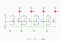
I am currently designing a circuit that can detect the amount of moisture found in water. It must work on 4 LED's (1, 2, 3, 4). The 1st LED will light brighter when the soil is dry, the 2nd will light dimmer when the soil is almost dry but not dry, the 3rd will light dimmer when the soil is almost moist but not moist and the 4th will light when the soil is moist. I managed to do a circuit that uses the 1st and the 4th LED. I used 2 LEDS (1st & 4th), 2 2N222 Transistors, a switch and some resistors.
I have 2 CD4013 components and I do not know how to use them in order to connect the the 2nd and 3rd LED. May someone help with a circuit and brief explanation using the CD4013 chips to make the circuit, I am really struggling with this.
Thank you