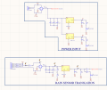
I have a PCB that converts 24VAC to 5VDC and 3.3VDC for use with a micro controller and other circuitry.
I need the microcontroller to read a conventional irrigation rain sensor. It is my understanding The rain sensor is basically a switch so my thought was to give it 24VAC and when it switched on (Rain) it would pass that 24VAC to my bridge rectifier which then gave power to a 3.3v regulator and the output of that went to my micro controller so it would know when a digital high was happennig. Brute force and not elegent I'm sure.
Anyways, As you can see, one side (of the AC side) of my bridge rectifier is always connected to AC gnd/neutral. The other side of the primary winding goes to a connector which I was going to connect to the rain sensor. so currently the primary is just a stub on the nuetral.
My problem is that even with one side of the primary just floating, and other tied to ac neutral/gnd, I am getting 36v out of the secondary and 3.3v out of my regulator when I don't want it.
Can someone help me understand and fix this. I appreciate the help and insight.


