HELP-Logic Level Power MOSFETs keep failing

Thread Starter

MartyMitchell

Joined Sep 11, 2012
23
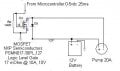
I'm trying to switch a 12v air pump (20A) on and off with a logic level power MOSFET and a microcontroller (0-5v). See attached schematic. Works great about 5 cycles, then blows up the MOSFET, leaving the Drain to Source partially open always. Heat sink on MOSFET, gets warm but not hot. Rds ON is 17 mOhm @ 10A, 10V.

What am I doing wrong? Any suggestions or ideas would be great! I can use another part if you know of one that would work better and not blow up.

Part info - http://www.digikey.com/scripts/DkSearch/dksus.dll?vendor=0&keywords=568-9506-5-ND
 

Attachments

Thread Starter

MartyMitchell

Joined Sep 11, 2012
23
Hi Mike - You're right. I checked out figure 3 and it looks like the safe zone is 50 amps for no more than around 100ms. So I guess I must be operating beyond the safe zone.

The diode is to protect the MOSFET from high voltage spikes when the pump circuit turns off.

Can you think of a way to solve this puzzle? Different part? Current limiter?

Thanks,
Marty
 

ErnieM

Joined Apr 24, 2011
8,415
If it works OK for 5 times, but then does not turn on the 6th time it sounds like the turn off spike is taking out the FET.

If the motor makes a positive spike the diode should catch it. If it makes a negative spike that will come thru the body diode of the FET. I don't have any real experience to say if the latter is possible, but I'm going to follow this thread to see what your results are. I need to drive a similar pump soon.
 

Thread Starter

MartyMitchell

Joined Sep 11, 2012
23
Hi Ernie,

Thanks for your thoughts. Might be the case, I'm not sure. Do you think I could solve the problem, if it is caused by inductance kick, by slowing down the microcontroller's high/low states? In other words, drive the signal into an R-C network to reduce the high speed switching.

Any other ideas would be great.

Thanks,

Marty
 

MikeML

Joined Oct 2, 2009
5,444
The inductive kick as an inductive load in the drain of an NFET turns off increases the drain voltage. The snubber diode is connected such that the drain voltage is clamped one diode drop above the battery voltage. However, if the snubber is a slow turn-on diode, then it may allow Vds to shoot up before the diode turns on. That is why I asked what part number you were using for the snubber.
 

MikeML

Joined Oct 2, 2009
5,444
The diode is a 1N4001. The reverse voltage rating is only 50v. Not sure how fast or slow they are.
If the motor running current is 20A, then the snubber will have to carry 20A as the FET shuts off. The 1N4001 is too light for that. Also, if the motor is a segmented commutator brush-type motor, the brushes make and break because the motor is spinning. I dont know what voltages might appear at the FET drain due to the brush arcing. Have you looked at it with a 'scope?
 
Last edited:

Thread Starter

MartyMitchell

Joined Sep 11, 2012
23
The diode has not blown when measured with the diode checker on my DVM. Still 0.7v and open the other way.

Mike-you're right, I will need to find a new diode that can handle 20a, the amount of current that may want to flow backwards when the MOSFET turns off. What about the voltage? Should I find one good for 400v?

I'll put the motor on a scope and see what kind of votages are present and report back.

Marty
 

JDT

Joined Feb 12, 2009
657
This pump will draw a very high current on start-up. Your MOSFET needs to be oversized in respect of it's current rating. Probably by about 6 - 10 times.

Also you need to drive the MOSFET properly. The gate has a high capacity (it will have if you use the correct MOSFET) and needs to be driven with a proper gate driver that can deliver AMPS to the gate so that it charges and discharges FAST.

Also vital that during power-up, the MOSFET cannot be switched on before the supply volts has ramped up to the correct supply voltage. Some gate driver IC's have undervolt lock-out included.

A partially driven, partially turned-on MOSFET will instantly destruct with a high current load due to localized heating. I know, I've done it!
 

donho

Joined May 16, 2010
5
Forget the MOSFET when controlling an inductive load. Use a simple bipolar transistor to drive a solid-state relay. The SS Relay will last for years and much less expensive than the high power MOSFET.
 
Top