Hi Guys,
I have attached here a filter i acquired from one of my professors. From first glance, I saw that the presence of the inductor and capacitor at the two ends seem to mimic the Tee section bandpass filter. Since I am trying to solve for the bandwidth to be used from the formulas available, i was wondering if what i am doing is in the right direction or if anybody can propose a solution?
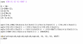
Currently this is what I have...

I am not sure if I am able to justify the parallel arrangement of the two 33n inductors with the 8.2n inductor.
Thanks for any advice and help!!
I have attached here a filter i acquired from one of my professors. From first glance, I saw that the presence of the inductor and capacitor at the two ends seem to mimic the Tee section bandpass filter. Since I am trying to solve for the bandwidth to be used from the formulas available, i was wondering if what i am doing is in the right direction or if anybody can propose a solution?
Currently this is what I have...
I am not sure if I am able to justify the parallel arrangement of the two 33n inductors with the 8.2n inductor.
Thanks for any advice and help!!


")