Help in Generating Pulses Using Schimmit Trigger

Thread Starter

Ravi Patel 1

Joined Apr 22, 2017
14
I am a Mechanical Engineer but doing this small project for my control system. I am working on a circuit which counts in coming pulses form a circuit with Schimmit Triggers with varying frequency as per sensor capacitor by Micro Controller.
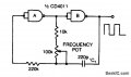
Here is its image.

All Capacitors are 0.1uF except C1, it is sensor with values varying between 200pF to 2000pF, ALL Resistors are 10K and IC is 74HCT14.

I have found this one in a reference paper but I am unable to make it working on my own.
I have built this with 74HC14, as I was not having 74HCT14, on bread board and count pulses by arduino but it is quite unstable, varying from 2k to 15k. I wish not to use simple "Schimmit Trigger Oscillator" as It will need to ground one end of C1, for my application it not possible. I have tested my Arduino Code with simple "Schimmit Trigger Oscillator" and it gives reasonably accurate and stable result, so code is OK.
Can anybody help me with this circuit? Does this can only work with 74HCT14? If I wish to use 74HC14 then what changes are must to be made for stable result. Or any other circuit using Schimmit Trigger that can do this same job?
 

ebeowulf17

Joined Aug 12, 2014
3,307
Well, I'll admit I don't understand the circuit concept well enough to offer design insights, but here are two thoughts:

Based on the datasheet, it looks like the two chips are identical except for acceptable supply voltage ranges. If you're running on 5V supply, it looks like they should be totally interchangeable.

As a simple diagnostic step, have you tried that circuit with a standard, fixed capacitor at C1, instead of the sensor you intend to use? Establishing basic circuit behavior before adding the variable of sensor performance might make it easier to troubleshoot.
 

MrChips

Joined Oct 2, 2009
30,720
I am assuming that the objective is to detect changes in C1.
Can you say exactly what is C1?
Why can it not be grounded?
What does C1 measure?
What is the typical range of C1?

There may be other approaches to your problem.
If you are already using a microcontroller (MCU), the simplest approach is to use two I./O pins on the MCU.
Connect C1 in parallel with a resistor and connect across two I/O pins.
 

AnalogKid

Joined Aug 1, 2013
10,990
HC and HCT parts are not identical. HC parts have CMOS transition levels. For a Schmitt input, these are approximately 1/3Vcc and 2/3Vcc.

The T in HCT stands for TTL. An HCT part has TTL transition levels. For a non-Schmitt part it is approx. 1.8 V. Been too long since I looked up the Schmitt input levels, but they are different from HC parts.

Separate from that, can you post a link to where the circuit came from. It looks to me like C2 and C3 swamp out the relatively small C1. Also, I don't see a need for R3 and R4, since the output stage can override these currents easily.

ak
 

Thread Starter

Ravi Patel 1

Joined Apr 22, 2017
14
Well, I'll admit I don't understand the circuit concept well enough to offer design insights, but here are two thoughts:

Based on the datasheet, it looks like the two chips are identical except for acceptable supply voltage ranges. If you're running on 5V supply, it looks like they should be totally interchangeable.

As a simple diagnostic step, have you tried that circuit with a standard, fixed capacitor at C1, instead of the sensor you intend to use? Establishing basic circuit behavior before adding the variable of sensor performance might make it easier to troubleshoot.
Yes they are operating at 5VDC, sorry I forgot to mention. 74HCT14 or 74HC14 is Hex Schimmit Inverter and I have used two of them. Yes I have used a fixed capacitor for initial debug process but output is not coming stable. Ultimately this circuit can be used to create pulses at certain frequency corresponding to variable C1 and so have meaning of measuring changing C1.
 

Thread Starter

Ravi Patel 1

Joined Apr 22, 2017
14
I am assuming that the objective is to detect changes in C1.
Can you say exactly what is C1?
Why can it not be grounded?
What does C1 measure?
What is the typical range of C1?

There may be other approaches to your problem.
If you are already using a microcontroller (MCU), the simplest approach is to use two I./O pins on the MCU.
Connect C1 in parallel with a resistor and connect across two I/O pins.
Yes, your estimated objective accurately. C1 is capacitive sensor and varies with changing concentration of a conductive fluid. Grounded C1 will have expose to conductive fluids and metal pipes so my GND reference might get shift depending on plant behavior. for Range it is 200pF to 2000pF
 

Thread Starter

Ravi Patel 1

Joined Apr 22, 2017
14
HC and HCT parts are not identical. HC parts have CMOS transition levels. For a Schmitt input, these are approximately 1/3Vcc and 2/3Vcc.

The T in HCT stands for TTL. An HCT part has TTL transition levels. For a non-Schmitt part it is approx. 1.8 V. Been too long since I looked up the Schmitt input levels, but they are different from HC parts.

Separate from that, can you post a link to where the circuit came from. It looks to me like C2 and C3 swamp out the relatively small C1. Also, I don't see a need for R3 and R4, since the output stage can override these currents easily.

ak
For the link, I have to ask my friend who send me document. I am not Electrical Engineer but from what I understand, you say right that output current will override but don't I need a current limiting resistor for slowly charging C1? Also what do you think if I remove R3, R4 and C3 then I may have improvement on stability? I will check it out practically but just want to hear you thoughts. Thanks.
 

Thread Starter

Ravi Patel 1

Joined Apr 22, 2017
14
I am assuming that the objective is to detect changes in C1.
Can you say exactly what is C1?
Why can it not be grounded?
What does C1 measure?
What is the typical range of C1?

There may be other approaches to your problem.
If you are already using a microcontroller (MCU), the simplest approach is to use two I./O pins on the MCU.
Connect C1 in parallel with a resistor and connect across two I/O pins.
Can you please tell me in detail about the approach of connecting Resistor and Capacitor parallel and connect across two MCU Pins. How will I detect change in attached Capacitor? Thanks.
 

ebeowulf17

Joined Aug 12, 2014
3,307
HC and HCT parts are not identical. HC parts have CMOS transition levels. For a Schmitt input, these are approximately 1/3Vcc and 2/3Vcc.
:oops: Sorry I jumped in prematurely on that one. Thanks for the quick correction. I'll have to take another look at the datasheet. I couldn't find any difference in transition levels on my first read through. Live and learn!
 

MrChips

Joined Oct 2, 2009
30,720
Can you please tell me in detail about the approach of connecting Resistor and Capacitor parallel and connect across two MCU Pins. How will I detect change in attached Capacitor? Thanks.
Use any two available input/output pins on the MCU. Let us call the two pins A and B.
The capacitor C is connected across pins A and B.
A resistor R is also connected across pins A and B. The value of the resistor will affect the time constant, resolution, and time taken to take a measurement. Resistance value can be 10kΩ - 10MΩ. I would suggest you begin with 100kΩ as a starting point.

In the MCU you will program the ports A and B to switch through the following sequence.

1. A = 0, B = 0
2. A = 1, B = 0
3. Delay to allow C to charge
4. A = input, B = 0
5. Detect using interrupts when A switches from 1 to 0.

6. A = 0, B = 0
7. A = 0, B = 1
8. Delay to allow C to charge
9. A = 0, B = input
10. Detect using interrupts when B switches from 0 to 1.

11. Increment counter
12. Repeat Steps 1 to 11

With an internal hardware timer, allow Steps 1 to 12 to run for a set duration.
At the end of the duration, examine the value of the counter.

Stop, reset, rinse, and repeat.

With careful setup and attention to details you can achieve 16-bit resolution.
 

Thread Starter

Ravi Patel 1

Joined Apr 22, 2017
14
This also will work. This is a version of the oscillator section of a CD4060. If you use Schmitt gates, the frequency will be lower than indicated by these equations.

ak
View attachment 131680
I have tried this circuit and it does give me Stable and Repeatable output. I have one more thing to ask you. On breadboard this works but on actual setup my variable Capacitor will not in vicinity on other components. I have to attach Capacitive Sensor with wires to board. Do you think this will work on remote/far capacitor? Should I keep any issue in my mind while trying out remote/far sensor? Of course I will try it my self as soon as I built actual sensor and not just fixed capacitor, just hear your thoughts. Thanks a LOT.
 

ericgibbs

Joined Jan 29, 2010
18,767
Hi Ravi,
I have used that type of oscillator, the only problem I had was that frequency was easily effected by changes in temperature of the IC.
When you have it working, place your finger on the IC body and note the change in frequency due to your warm finger.
E
 

Thread Starter

Ravi Patel 1

Joined Apr 22, 2017
14
Hi Ravi,
I have used that type of oscillator, the only problem I had was that frequency was easily effected by changes in temperature of the IC.
When you have it working, place your finger on the IC body and note the change in frequency due to your warm finger.
E
I have heated up IC, 74HC14, with hot air to approx 50C and still circuit, suggested by AnalogKid, gives stable result. I think large operating temperature range can take care of change in temperature.
 

AnalogKid

Joined Aug 1, 2013
10,990
I have used that type of oscillator, the only problem I had was that frequency was easily effected by changes in temperature of the IC.
True for the 04, much less true for the 14. It's transition levels are set by circuit elements other than just the FET transconductances.

ak
 

Thread Starter

Ravi Patel 1

Joined Apr 22, 2017
14
This should work for you:
View attachment 131673
Neither end of Csensor will be at 0V. Choose R3 to get the frequency range you want.
I have tried your suggested Circuit and there are stability issues. One thing I can ask is How critically important C2 is? How you decided its value? I don't have exact cap available with me, so i tried with different ones but problem still remains.
 

Alec_t

Joined Sep 17, 2013
14,280
C2 isn't critical and was chosen to minimise cost and space occupied. The C2R2 time constant should be at least 10 times the CsensorR3 time constant to keep the R1R2 junction at a reasonably fixed voltage. Try increasing C2 to improve stability. Also, ensure all unused inputs of the IC are connected to ground or the +ve supply rail.
 
Last edited:
Top