 Facebook
 Google
 GitHub
 Linkedin
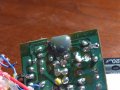
 A family member asked for help fixing one of those decorative indoor water fountains. The symptoms were "it doesn't work." Anyways, aside from the possibility of simply a bad pump, I'm looking at the electronics. Can anyone help me identify the two components below? The disc (which reminds me of a ultrasonic nebulizer, but why?) and what might reside under the grey blob? : )
Thanks!!!
Attachments
-
 173.2 KB Views: 45
")


