Help identify transformer

Thread Starter

Bassquake

Joined Feb 16, 2018
97
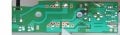
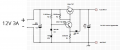
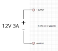
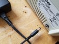
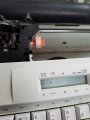
Is it possible I can bypass the power supply unit altogether and just use a standard 12v power adapter? Problem is I dont know what the amp rating needs to be. Its a 2 pin output off the power board to a mainboard pcb.

See pic:
 

Attachments

MrChips

Joined Oct 2, 2009
34,813
If you look at the back of the typewriter you will find a label stating the AC mains power requirements, 230V @ 0.18A.
That is 41.4W which is equal to 3.45A @ 12V.

I believe Max is right on the money at 3A. You now have to confirm the low voltage output.


ebp

Joined Feb 8, 2018
2,332
I also agree that the supply is very unlikely to be more than 3 amps. 12 volts should be OK. I assume you are going to continue to use the regulator on the power supply board. Don't use a regulated 12 volt supply fed directly to the circuitry down-stream of the original regulator since it may cause too much power dissipation in the (assumed to exist) on-board regulator(s). Assuming the zener really is 7.5 volts, the output of the regulator would be about 8.2 volts.
 

Thread Starter

Bassquake

Joined Feb 16, 2018
97
Sorry I've taken a while to respond.

I've attached the circuitry layout. I followed mostly DodgyDaves sketch. Also attached high rez closeups of each side.

Can I use a AC 12V 3A power adapter and apply it to where the rectifier bridge is? Do I need to put it before the rectifier or remove the rectifier altogether and use a DC 12V 3A adapter instead?
 

Attachments

MaxHeadRoom

Joined Jul 18, 2013
30,661
If your substitute supply is regulated then you just wire it across the output, you could either remove or isolate the trace to the regulator original circuit.
Max.
 

ebp

Joined Feb 8, 2018
2,332
Until you verify the output voltage of the original regulator, I recommend connecting the external supply to the input side of the bridge (which will drop about 1.5 volts), or to the output side of the bridge. I'm reasonably confident in my original estimate that the ouput will be about 8.2 V based on the zener color bands. If you connect 12 volts to the main board the excessive voltage could cause excessive power dissipation in the local regulators. And presumably there are electromechanical devices of some sort that may be supplied by the regulator and would be quite unhappy with excessive voltage.
 

Thread Starter

Bassquake

Joined Feb 16, 2018
97
Ok, I picked up a 12V 3A power adaptor (see photo, it says AC adaptor, should I specifically get a DC one?).

So which way is good to connect? Ive attached 3 images of possibilities to connect:
  • psu_a = before bridge
  • psu_b = after bridge
  • psu_c = bypass altogether
Hopefully that should be it! Appreciate all the help.
 

Attachments

AlbertHall

Joined Jun 4, 2014
12,625
The adaptor is AC input, DC output.
The second diagram, connecting the adaptor after the bridge will be best. Do not connect it after the regulator.
 

ebp

Joined Feb 8, 2018
2,332
Oh, absolutely a team effort. I should have made that clear. I was simply gloating over my estimate of what the output voltage would be.
 
Top