Help for Voltage regulator LM338 with current limitation of 5A

Thread Starter

romain514

Joined Dec 16, 2015
18
And here we have 3 ways to do the transformer. Notice the different wattage rating of the two diode design. The four diode design uses the transformer more efficiently and that translates into $$.

There is about 1/2 volt difference in the voltage at the first capacitor. Well within safe range.
Thanks for your answers! yeah im a bit lost for the transformer in eagle... I can't find the good part for it so I didn't put it in the design of the circuit to not make people think I intentionnaly use the wrong one. This is my transfomrer on Digikey: https://www.digikey.ca/product-detail/en/F-260U/237-1950-ND/5032185

so it will mostly look like your 3rd circuit.


@all
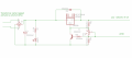
Here's my final design, thanks for your patience with me and to teach me what you know! I'm a complete noob in electronics and i'm starting to design my own things but I still need help in a lot of things.

Is there anything to modify/change or replace, and can anyone tell me if that's good to go?

Thank you so much everyone!
Capture d’écran 2015-12-16 à 20.42.24.png
 

Thread Starter

romain514

Joined Dec 16, 2015
18
Is the circuit in post number 13 is better than the last one I've posted? for what I want to do, what do you think?
Thanks! :)
 

#12

Joined Nov 30, 2010
18,224
Wrong transformer. Read my drawing slowly and carefully. The transformer current must be de-rated because you are using the PEAK voltage it produces.

I sincerely recommend the first drawing because the only difference is one switch, and the result will be that you can get a lot more current through the LM338 when the output voltage is dialed down below 12 volts if you flip the range switch to, "low". If you don't like having all that current available before the chip overheats, you can just leave the range switch in the, "high" position.

Page 7, 10 ma minimum load. Change R2 to 120 ohms.
 

Attachments

Thread Starter

romain514

Joined Dec 16, 2015
18
Wrong transformer. Read my drawing slowly and carefully. The transformer current must be de-rated because you are using the PEAK voltage it produces.

I sincerely recommend the first drawing because the only difference is one switch, and the result will be that you can get a lot more current through the LM338 when the output voltage is dialed down below 12 volts if you flip the range switch to, "low". If you don't like having all that current available before the chip overheats, you can just leave the range switch in the, "high" position.

Page 7, 10 ma minimum load. Change R2 to 120 ohms.
Oh oh... So I need to buy another transformer? I already have this one. Can I make modification on the circuit so it will fit or am I forced to buy a new one?
I mean, I may not fully understand what you're trying to explain me... Sorry but like I've said I'm a complete noob in this. So I'm trying to learn here at the same time...

So what transformer should I buy, and could you give me a digikey product if you have time? It would be really helpfull.

If instead I can make a sort of modification to the circuit to be able to use that transformer that I already have it would be great!

Thanks again for all your help! :)
 

JUNELER

Joined Jul 13, 2015
183
Hi all,
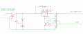
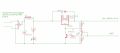
I want to do a voltage regulator with a transformer that gives me 24VAC@6A and a LM338. But since the LM338 can support 5A I would like to limit the current to 5A. I did a little circuit here and placed the resistor R4 (0.24Ohm) where i think it would limit the current. I also have a potentiometer to regulate the voltage from 1.25V to 30V.
Can anybody help me and tell me if my circuit is good and if it would function as it is?

By the way: I'm a noob in electronics so please be patient we me! :)

Thanks all
View attachment 96681
I think it is better to have a secondary transformer of 24v ac that give 5a. you can make a
winding of such 24ac at 5a rather than 6a. 2nd thing what load you will use to this ckt.
it depends on the load you will use.dont worry about the 5a output of the ckt.
so better clarify which load you wil use.

Hi all,
I want to do a voltage regulator with a transformer that gives me 24VAC@6A and a LM338. But since the LM338 can support 5A I would like to limit the current to 5A. I did a little circuit here and placed the resistor R4 (0.24Ohm) where i think it would limit the current. I also have a potentiometer to regulate the voltage from 1.25V to 30V.
Can anybody help me and tell me if my circuit is good and if it would function as it is?

By the way: I'm a noob in electronics so please be patient we me! :)

Thanks all
View attachment 96681
Hi. i suggest you provide a secondary output of 24vac @5a instead of 6a. secondly what load you will use in this 5a ckt and limit your load requirement. your ckt is good
only transformer changes on secondary side,your drawing is like you place the transformer in filter look arrangement.
 

JUNELER

Joined Jul 13, 2015
183
Hi all,
I want to do a voltage regulator with a transformer that gives me 24VAC@6A and a LM338. But since the LM338 can support 5A I would like to limit the current to 5A. I did a little circuit here and placed the resistor R4 (0.24Ohm) where i think it would limit the current. I also have a potentiometer to regulate the voltage from 1.25V to 30V.
Can anybody help me and tell me if my circuit is good and if it would function as it is?

By the way: I'm a noob in electronics so please be patient we me! :)

Thanks all
View attachment 96681
I suggest to use a secondary output of 24vac@5a instead of 6a.secondly what load requirement you will use.your ckt drawing appear that you use a choke coil filter,not the stepdown instead.
 

Thread Starter

romain514

Joined Dec 16, 2015
18
3.72 amps is what your transformer will produce with drawing 1 or 3. or it will produce 10 volts DC at 6 amps with drawing number 2.

I think the second transformer on this page will work nicely for 24 volts and 5 amps. Notice the 192 watt rating...EXACTLY what I said. F261U, Triad, and $1.70 cheaper than the one you picked out.

https://www.digikey.com/product-search/en?pv1617=60&pv1617=117&pv1617=32&pv1617=88&pv1617=167&pv1617=131&pv1617=151&pv1120=917&pv1120=1581&pv1120=845&pv1120=1003&pv1120=1011&pv1120=846&pv1120=1169&pv1120=907&pv1120=219&pv1120=442&FV=fff4000c,fff8012f&mnonly=0&newproducts=0&ColumnSort=0&page=1&quantity=0&ptm=0&fid=0&pageSize=25
All right, so I've ordered the new transformer F261U and since I'm canadian, this cost more then 15$ difference between the one I bought couple days ago.. I really hope that this will do the job!
Thanks for the help sir!
 

Thread Starter

romain514

Joined Dec 16, 2015
18
Change the pot to 2K2, that will give you 24V.

Change R4 to 0.14 ohms to limit current to 5 amps max.

0.12 ohms will give 5.8 amps max.
Thank you very much @Dodgydave!
I will do the modifications tomorrow and will sen a final circuit image here to ask you guys if there is any thing else or if it's ok like that.

My last question:
If I want to add a fuse to protect my circuit can I put a fuse rated 5A somewhere in the circuits? And if yes, where should I put it?

To make a simple story; my friends likes to play with elements. And he's trying to do some electrolysis or something like that to get the gaz out for his project. so the basics of this seems to do a generator which consist of 10-20 sheet metal with spacers one next to the other in a container full of distillate water with potassium or something like that, and then pass a current @ a certain voltage through the metal plates.
I'm only making the circuit and he told me about his project but I really don't know if I need a fuse there to protect circuit/human

Please give me some advices.
Thank you all again!
 

ScottWang

Joined Aug 23, 2012
7,505
I suggest to use a secondary output of 24vac@5a instead of 6a.secondly what load requirement you will use.your ckt drawing appear that you use a choke coil filter,not the stepdown instead.
Please don't using all capital characters in the post, thank you. (your posted have been modified to the lower case)
 

ScottWang

Joined Aug 23, 2012
7,505
I think it is better to have a secondary transformer of 24v ac that give 5a. you can make a
winding of such 24ac at 5a rather than 6a. 2nd thing what load you will use to this ckt.
it depends on the load you will use.dont worry about the 5a output of the ckt.
so better clarify which load you wil use.


Hi. i suggest you provide a secondary output of 24vac @5a instead of 6a. secondly what load you will use in this 5a ckt and limit your load requirement. your ckt is good
only transformer changes on secondary side,your drawing is like you place the transformer in filter look arrangement.
Please don't using all capital characters in the post, thank you. (your posted have been modified to the lower case)
 

#12

Joined Nov 30, 2010
18,224
One place to put a quik-blo fuse is just before the LM338 so it doesn't have to handle the start surge into the 10,000 uf capacitor...if limiting the output is your primary concern. The Dodger said to put the fuse before the capacitor. If you do that it better be a slo-blo type, or just back up clear to the 120 volt side of the transformer and cover all the possibilities for failure, including the transformer, main capacitor, and the rectifiers. About 2 amps, slow, should do the job.

The darn thing is already protected with a self limiting LM338 and a current limiter tacked on to the ground side. Don't burn too many brain cells trying to get this fuse perfect. If the protection you already have in the regulator side fails, it's going to pop any size fuse, clear back to the circuit breaker box. Adding a local, 2 amp fuse, will save you a trip to the breaker box and probably keep the capacitor from splattering all over the place instead of just making a sizzling noise and a bad smell.

ps, I already proved JUNELER is wrong by using the transformer sizing guide in post #23
 

MikeML

Joined Oct 2, 2009
5,444
It will never come close to delivering 5A when the output is adjusted down to 1.25V.

If you could get 5A, the power dissipation in the regulator would be about (24*1.2 - 1.25)V*5A = 137W. Even if bolted to an infinite heat sink, the chip will heat itself to the point where it shuts down...

Reread the section of the data sheet I linked to earlier that talks about thermal current self-limiting...
 

marcf

Joined Dec 29, 2014
300
Per the LM338 data sheet, the internal dissipation of the device is rated at 50W max.
An input to output voltage difference of 10V and a load of 5amps would limit the amount of power that could be supplied to a load. Even then you would need a 1 C/W heat sink. ($156.00 at digikey) to limit temp rise to 125C (it's max operating temp) at 25C ambient.
Θjc = 1.0 C/W
Θja = 35 C/W
With a input voltage of 34VDC (1.414*24Vrms), it would limit the output to less than 24V@5amps and make a very nice space heater.
257F is hot!!!

It would make an interesting oscillator circuit tho. The heatsink would raise T ambient above 25C, the device would shut down, the T ambient would go down and the process would repeat. ...
 

Thread Starter

romain514

Joined Dec 16, 2015
18
Ok, thanks for you answers all.

I just want to make a power supply out of this. I don't really need 5 amps neither going down to 1.25v, I just need it to do some electrolysis. So what's my best option with what I have?
 
Top