help for buffer improve

Thread Starter

DaniKowa

Joined Sep 23, 2020
218
Hi,

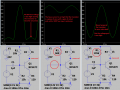
I created a circuit with a double buffer that should serve to drive low loads (in the simulated circuit with R4) but I have some problems and I would need a hand to solve.
Problem 1: coupling the two buffer stages distorts the amplitude. I tried to insert an interstage resistor of different values, but did not solve.

2nd problem: the two BD transistors fail to drive the 10ohm load.

I have assumed that the 3904 and 3906 fail to deliver enough current to drive the two BD139 and 140 .

The goal is to use this buffer that will be driven with an MPSH10 or if possible with a J-FET MPF102 without distortion. And the latter thing often happens to me when I pair several stages. I'd like to understand why. The input voltage of the buffer will be maximum sine 9volt but is the maximum. The two BD's are already in the LtSpice database, while of the 3904 and 3906 I'm not sure. I also attach the related model files if needed.

I have another request if possible. Is it possible to have an example schema for a buffer like this, but based on MOSFETs?

Thanks for the help!
 

Attachments

Papabravo

Joined Feb 24, 2006
21,159
Your class-B stages lack compensation diodes and I don't think you want the 2K2 resistors in the emitter stages. You could also AC couple the stages to keep the biasing stable.
The 2N3904/2N3906 can supply 200 mA of base current to the BD139/BD140 and that is more than enough.

Edit: Try something like this;

1626462643901.png
 
Last edited:

BobTPH

Joined Jun 5, 2013
8,812
Here is your circuit fixed to use the 2n3094/6 and BD139/40 as Darlingtons. There is a lot of distortion at 10 MHz, but it works quite well at 1 MHz.

1626464154032.png
 

Audioguru again

Joined Oct 21, 2019
6,673
The input signal swings positive and negative but there is no negative power supply for the transistor outputs to go negative.
If you insist on having only a positive supply then you must add an input coupling capacitor.
 

Attachments

Thread Starter

DaniKowa

Joined Sep 23, 2020
218
You have no connection between the 2n3904/n23906 and the bd139 / bd140. How do you expect that to work?
Bob
I know it's not connected. If you connect the first stage to the second, you will see a deterioration of the sinusoidal.

Here is your circuit fixed to use the 2n3094/6 and BD139/40 as Darlingtons. There is a lot of distortion at 10 MHz, but it works quite well at 1 MHz.

View attachment 243728
There is a way to lower the distortion in that circuit? I've drawn a circuit proposed by @Papabravo (thanks) but modified with the 139 and 140 transistor, and it works with a loss of amplitude in 25%. By substituting the 3904 with BC847C and seem to work very well. Now the only problem is the BC847C is available only in SOT23 package. The alternative i've found is BC107 or BC549C. What do you think?

The input signal swings positive and negative, but there is no negative power supply for the transistor outputs to go negative.
If you insist on having only a positive supply, then you must add an input coupling capacitor.
The single power supply is very convenient but has limitations as you have exposed. In this, you could also use the dual without any particular problems.


Audioguru again

Joined Oct 21, 2019
6,673
Your amplifier with the dual-polarity power supply has the base of its input transistor 0VDC without an input coupling capacitor then R4 and R5 do nothing and Q3 is saturated and does not amplify.
The amplifier has no negative feedback then it will produce distortion.
 

Thread Starter

DaniKowa

Joined Sep 23, 2020
218
This happen when i use a coupling capacitor.


A way to correct the wave is modifing R4 10k to 1K if is suitable.


But the initial request was not amplify but only buffering. Where you see distortions in post #6 ?
 

Audioguru again

Joined Oct 21, 2019
6,673
Post #6 has a low output of only 2Vp-p but uses a very high 24V supply so the distortion is about 1%. With negative feedback then the supply voltage can be much less for an output of only 2Vp-p and the gain can be 1 as a buffer and distortion can also be much less.
 

Thread Starter

DaniKowa

Joined Sep 23, 2020
218
Yes right observation! . To make no mistake about the input voltages I have the maximum at 12V p-p as the maximum level and set R4 to 500Ohm if it is correct. From the simulation I do not seem to see any particular problem with both the capacitor C2 and without. I hope it's all right this time.As for the power of the resistors I see no particular problems with 1/4Watt except on R2. For the latter I varied the value from 100 to 120ohm measuring a peak current of 100mA therefore a resistance from 2watt I think is the most indicated.

 
Last edited:

Thread Starter

DaniKowa

Joined Sep 23, 2020
218
Hi, in the previous post #10 the simulator would confirm that a 500ohm R4 returns cmq a correct signal output and not distorted with respect to the input. Since usually that resistor has a much higher value of at least a few K , can it still be considered working even with 500ohm if the input voltage increases? I have seen that increasing the input voltage R4 must be reduced probably to correct the input on the transistor. Thank's
 

Audioguru again

Joined Oct 21, 2019
6,673
With the input bias resistor at 500 ohms then the input transistor is turned on very hard and is simply a piece of wire between its collector and emitter. It does not amplify and does not invert the signal.
The input resistance is the 500 ohms parallel with 15k and parallel with the 120 ohm emitter resistor which is about 96 ohms.
 
Top