 Facebook
 Google
 GitHub
 Linkedin
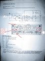
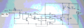
I have an "FM oscillator 2W (88... 108 Mhz)" kit from "GENIUS ELECTRONICS"
I have some questions about it. First, may you make a look on the circuit and give me your view if it will work fine or what?
I compared the connections in the circuit and the real connections on the PCB (as shown in the PCB layout in the picture), I found a difference.. a mistake in the connections. The connection mistake is more probably to be with the circuit diagram and not with the PCB since the kit is being in the market from a long time.
Here is the problem: According to the circuit diagram, the positive terminal of the battery is connected to the emitter of T2 and to C5... while on the pcb it is connected to the second side of R5, it is connected to the emitter of T1 and C4, R4, and the +ve terminal of the battery is connected to one of the terminals of the mic.
This is the most important thing to know for now but I want to ask two other questions:
L1 is printed on the pcb as shown in the picture, T2=sf118 have a metal case as bc109/bc107 but its size is about 3 times that of bc109 (I didn't found its datasheet). Do you think this fm 'oscillator' is really 2W? if it's 2W its range should be 3KM or even more right? There is no supplied information about the antenna.... what do you think?
Point 'A' (on the pcb) it connected to ground, what do you think it is?
Attachments
-
 115.4 KB Views: 133

") . Actually, I tried a lot to build a powerful transmitters earlier, my theory background was insignificant, but now it's better.. I still have problems with rf circuits even though I love it. One of the problems is that I hate working with coils and I find it hard many times. The main problem is with the parts needed, wires for coils with different thicknesses and-ferrite core-rf transistors...etc because I live in a remote village far from electronic components stores...etc
. Actually, I tried a lot to build a powerful transmitters earlier, my theory background was insignificant, but now it's better.. I still have problems with rf circuits even though I love it. One of the problems is that I hate working with coils and I find it hard many times. The main problem is with the parts needed, wires for coils with different thicknesses and-ferrite core-rf transistors...etc because I live in a remote village far from electronic components stores...etc


