the inputs in the software are triggered when the corresponding pins either get a 5V pulse or when they are grounded momentarily (you can easily adapt the software to choose either of these 2 options).
So I guess I can choose the one that gives the easiest solution.
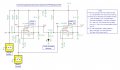
The simplest way would be to use the same kind of 555 circuit your using for the other limits but couple the 555 output pin to the LPT pin via a .1uF cap. This will give you a negative going pulse when the 555 times out.
but wouldn't this also trigger the pin on the lpt gate when I reset the system?
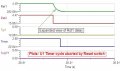
"The reset input (555 pin 4) overrides all other inputs and the timing may be cancelled at any time by connecting reset to 0V, this instantly makes the output low and discharges the capacitor."
There was a time that if I were needing what you require I would have prototyped the 555 circuits that I gave you. Those days are long gone and I would not use that approach today.
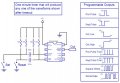
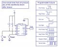
Attached are two Microcontroller schematics that use a ($3.25) Picaxe 08M. The stark difference between the my 555 circuit and these two schematics are dramatic. As you can see, the circuits are not identical, yet I can eliminate the edge triggering resistors and the caps in PicaxeTimer1, which gives us PicaxeTimer2. What's unique to uC's is I can still make PicaxeTimer2 respond to the same input signals of PicaxeTimer1 and yet produce the identical desired output from either.
The only reason that I used a 555 in this thread is because that's what you inquired about. That, and the fact that there seems to be a fixation with this very old technology here on AAC.
First of all, thanks a lot for helping me out with this. You've put a lot of effort in it to help me and I really appreciate that!
About the 555: I would not mind working with other IC's but I know the 555 is an easy to get timer.
2 more questions:
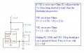
1) how can I now determine the Time out of the first timer? I see I can change it by changing C6 and R4 but what is the formula to calculate the time? (I would like to replace R4 with a potentiometer to vary the time between about 1 and 5 sec).
2) how can I switch the Reset switch with an NPN sensor circuit like this one
to use the inductive sensor? What do I do with the 24V in contrary to the 5V the rest of the clogic circuit is running on?
First of all, thanks a lot for helping me out with this. You've put a lot of effort in it to help me and I really appreciate that!
About the 555: I would not mind working with other IC's but I know the 555 is an easy to get timer.
2 more questions:
1) how can I now determine the Time out of the first timer? I see I can change it by changing C6 and R4 but what is the formula to calculate the time? (I would like to replace R4 with a potentiometer to vary the time between about 1 and 5 sec).
T = 1.1 × (R × C)
When you use a Pot you have to add a fixed resistor in series with it. This resistor prevents the Vcc from being shorted to ground (if the Pot wiper is set near zero Ohms) when the 555 discharges C.
2) how can I switch the Reset switch with an NPN sensor circuit like this oneto use the inductive sensor? What do I do with the 24V in contrary to the 5V the rest of the clogic circuit is running on?
The images that you posted has nothing to do with possible damage to a NPN transistor vs a PNP. Read again what it says In the application shown. They're more concerned with a sheath break causing a short to Gnd, thus causing a false actuation of a machine. It does not apply to anything I give you.
The images that you posted has nothing to do with possible damage to a NPN transistor vs a PNP. Read again what it says In the application shown. They're more concerned with a sheath break causing a short to Gnd, thus causing a false actuation of a machine. It does not apply to anything I give you.
The specs that you posted indicate a NPN Output. They don't state if it's an Open Collector but it's most likely. You should be able to connect the output of the sensor to the Trigger Switch node on my schematics. Same goes for the Reset Switch node.
Make sure you prototype and test the circuits on a bench prior to hooking it up to your machinery. If you want total isolation then use an OptoIsolator.
 Facebook
 Google
 GitHub
 Linkedin


") .
.


