help designing 2 simple circuits using 555 timers or others

Thread Starter

matd

Joined Feb 26, 2011
18
Hello everyone,

for a project I need to design 2 simple logic circuits. However, it's been a while since i followed some electronic courses so I could really use your help.

This is what te first one is supposed to do:

I have 2 switches, S1 and S2 (in blue), and an Input I1 to my lpt gate on my computer.
When the sliders moves from left to right, I want to ground the pin connected to I1 in my lpt gate for a short time (sort of a grounding pulse), after that, the input to the lpt needs to be open (or high?) again.
When the slider moves from right to left, nothing should happen and the input to the lpt gat should remain unchanged (left open).

So the logic combination should be this I think
Slide moves from left to right:
S1=0, S2=0 -> I1=1
S1=1, S2=0 -> I1=1
S1=1, S2=1 -> I1=0 (short grounding pulse)
S1=0, S2=1 -> I1=1
S1=0, S2=0 -> I1=1 (back at starting situation)

Slide moves from right to left:
S1=0, S2=0 -> I1=1
S1=0, S2=1 -> I1=1 (Slide moves in wrong direction)
S1=1, S2=1 -> I1=1
S1=1, S2=0 -> I1=1
S1=0, S2=0 -> I1=1 (back at starting situation)

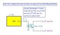
Someone else already helped me a bit and proposed me the following circuit (using a 555 timer ic).
He did point out that I should think about debouncing the switches I use depending on the types of switches.
I'm using normal microswitches so do these need debouncing?


Will this work for me?
And what will the input I do in this case, will it give a short 5V pulse or a short grounding pulse? (because I can change the input for the pin on my lpt gate fairly easy in the software so it needs a 5V pulse instead of a grounding pulse).


The second one is as follows

I have 2 inductive ring sensors with a switching output of the NPN or PNP type (it does not matter which one to me, whatever is best and easiest for designing the circuit) and the same input I1 as in the previous circuit.

when the first sensor detects a piece, it should start a timer.
Now there are 2 possibilities.

1st case
After some time t (which i think I can set using a potentiometer?), the second sensor still did not detect the part passing.
The circuit should now change I1 (so ground pulse or 5V pulse).

2nd case
The second sensor detects the part passing within the time t and stops and resets the timer.
Nothing should happen now untill the first sensor detects another part and starts the cycle all over again.

I hope all this is a bit clear for you?
If not please do not hesitate to ask questions, i could really use your help.

Thank you
 

Kermit2

Joined Feb 5, 2010
4,162
All switches(most) need to be debounced for use in a microprocessor input.

A simple RC network will suffice. Choose values that give you .1 to .2 seconds of charging time before reaching Vcc. The switch bounce will usually be less than this.

Also the trigger input of the 555 needs to go to ground to be activated. Your trigger input does not see a ground level in its drawn configuration. It may not function as expected I mean.
 

Thread Starter

matd

Joined Feb 26, 2011
18
ok so switching the S2 switch and the 4K7 resistor should do the trick, forming a pull down circuit?
 

Thread Starter

matd

Joined Feb 26, 2011
18
Ok so I tried rethinking the circuit a bit using this link
http://www.kpsec.freeuk.com/555timer.htm#monostable

I came up with this:


The circled red part explained:
"
Edge-triggering

edge-triggering circuit If the trigger input is still less than 1/3 Vs at the end of the time period the output will remain high until the trigger is greater than 1/3 Vs. This situation can occur if the input signal is from an on-off switch or sensor. The monostable can be made edge triggered, responding only to changes of an input signal, by connecting the trigger signal through a capacitor to the trigger input. The capacitor passes sudden changes (AC) but blocks a constant (DC) signal. For further information please see the page on capacitance. The circuit is 'negative edge triggered' because it responds to a sudden fall in the input signal.
The resistor between the trigger (555 pin 2) and +Vs ensures that the trigger is normally high (+Vs)."

The blue part explained:

"
Power-on reset or trigger

It may be useful to ensure that a monostable circuit is reset or triggered automatically when the power supply is connected or switched on. This is achieved by using a capacitor instead of (or in addition to) a push switch as shown in the diagram. The capacitor takes a short time to charge, briefly holding the input close to 0V when the circuit is switched on. A switch may be connected in parallel with the capacitor if manual operation is also required."


So how the complete circuit works:


when the slide moves from left to right, S1 is pushed first. Because this is a normally closed trigger, it frees the output the change value. When the slide moves further towards the right, S2 becomes active and makes the ouput high during time t (negative edge triggered).
The slide moves further towards the right and S1 goes open again, resetting the whole circuit.


When the slide moves from the right to the left, S2 comes up first but because S1 is not pushed, the system is still in reset (S1 Normally Closed).
Moving the slide further to the left pushed S1 too. This however does not change the output because the system only reacts to negative edges of S2 (S2 is already high now).
Also when S2 is released, this gives a positive edge so the output still does not change.

By the way I don't think I need debouncing.
Only S2 would need debouncing but the fact that pulsing the output multiple times (to 5V) is not really a problem to me (software only reacts to the first pulse) I don't think I should worry about this.
Or am I completely wrong here?


Does all of this make any sense?
 

Thread Starter

matd

Joined Feb 26, 2011
18
About the ringsensors.

I think I'm going to have to use NPN type sensors:

"NPN sensor :- This is a sensor whose output pulls down to the negative ( 0 volts) supply rail when it senses a metal target. Thus any attached load to the sensor output must be connected between the Positive supply rail & the output of the sensor to operate. This type of sensor cannot survive a short up to the positive supply rail ( a very rare occurrence!). Shorts to the negative rail (zero volts) will not damage it at all & it can tolerate this indefinately."

So this would ground the tirgger and Reset inputs.

Problem now is that most sensors work from 10 - 30V.
The 555 timer can handle up to 15V so any supply voltage between 10 and 15V would do.

But this would also give the ouput of the 555 timer a voltage between 10 and 15V, which my lpt port can't handle I think.

So can I just use a transistor on the output of the 555 that connects the lpt ground to any pin when it gets 10 -15V on its input?

Or how can I do this best?

Thank you
 

Thread Starter

matd

Joined Feb 26, 2011
18
yes I do think it should be NC.

When it is not pressed, it keeps the reset input low, which keeps the 555 in reset.
Only when it is pushed the output of the 555 can change.
(S1=1, S2=1, pulse on output)
 

CDRIVE

Joined Jul 1, 2008
2,219
Snip....When the sliders moves from left to right, I want to ground the pin connected to I1 in my lpt gate for a short time (sort of a grounding pulse), after that, the input to the lpt needs to be open (or high?) again.
When the slider moves from right to left, nothing should happen and the input to the lpt gat should remain unchanged (left open).
The 555 circuit you posted in post 5 will go high (pin 3) when S1 (Reset) is pressed (held open) while S2 (Trigger) is pressed momentarily or held closed. The output will remain high for the period of the RC time constant (T = 1.1 × (R1 × C1)) of the timing RC unless S1 is released. If S1 released while the RC charge period the timer output will go low before RC timeout. I believe this is opposite of the logic you are wanting. Also, I don't see the purpose of the cap across S1. Normally, a cap located there is used to put the 555 in reset when powered up. Since S1 is NC the cap serves no purpose.

Why are you using a 555 instead of common logic blocks? Is this a class assignment?

EDIT: You indicate push button switches in the schematic but your verbal description seems to indicate slide switches.
 
Last edited:

Thread Starter

matd

Joined Feb 26, 2011
18
no this is not a class project.
I'm making a machine with a moving gantry (like a clossic cnc machine). The bridge has to stop when moving from the left to the right and can go on without stopping when it goes from right to left.

Indeed these are push switches and not slide switches.
Something like this


someone told me I could use flip flops for this but that 555timers could give a much easier solution/circuit.

So if you could help me building accomplish this with other logic circuits I would really appreciate it.

thank you
 

CDRIVE

Joined Jul 1, 2008
2,219
Actually, the switch image that you posted isn't a push button switch. It's generically called a 'Micro-Switch'. When used in an application like yours they're called 'Limit Switches' that describe their function.
 

CDRIVE

Joined Jul 1, 2008
2,219
I'm assuming that the computer is going to be controlling servos...correct? If you could draw and post a bock diagram it will help greatly. This way none of us will be wasting our time giving you the wrong information.
 

Thread Starter

matd

Joined Feb 26, 2011
18
The PC is controlling stepper motors (about the same as servo's only without feedback and some other different properties).
I've tried drawing a block diagram, hope this clears things up a bit.

So the circuits I want to make are the "Direction detection circuit" and the "sensor circuit".
(Just to be clear: the block "limit switches" does not have anything to do with the circuits I want. It's just to make shure that the machine does not slide off it's own guiding rails when the movement is programmed beyond the dimensional limits of the machine, just like any ordanary limit switch does)
 
Last edited:

CDRIVE

Joined Jul 1, 2008
2,219
<SNIP>The 555 circuit you posted in post 5 will go high (pin 3) when S1 (Reset) is pressed (held open) while S2 (Trigger) is pressed momentarily or held closed. The output will remain high for the period of the RC time constant (T = 1.1 × (R1 × C1)) of the timing RC unless S1 is released. If S1 released during the RC charge period the timer output will go low before RC timeout. I believe this is opposite of the logic you are wanting. <SNIP>
Assuming that this is the logic you want, with the exception of the 555 going high when triggered, then all you need is an open collector inverter. Note: As is... your 555 will trigger only when S1 is in an open state. I just want to be certain that this is what you want.
 

Attachments

Thread Starter

matd

Joined Feb 26, 2011
18
Note: As is... your 555 will trigger only when S1 is in an open state. I just want to be certain that this is what you want.
What do you mean by open state?
I assume you mean that the switch itself is pressed, openening the connection between pin 4 and ground and so resetting the 555.

As the value of pin 3 (output) can only change when both switches are pressed, I do think this is the right circuit.

The "direction detection circuit" has to give a signal when the slide is moving from the left to the right AT THE TIME when both switches are pressed. (so slide stops when both are pressed).

And with the circuit you just posted, the 555 output that goes high will switch the transistor and this transistor in turn will connect the LPT ground pin to the right input pin.

I think (hope) it will work this way.

The second problem, the one with the ringsensors, has changed a bit: The first one should be replaced by a limit switch.
So when the limit switch is pressed, a timer should start running.
If after some time t (preferably variable with a potentiometer) the ringsensor still did not detect a part coming by, the circuit's output has to give a pulse (+5V)
If the sensor does detect a part coming by within the time t, the circuit should reset itself and be ready to start a new cycle by pressing the limit switch again.

Thank you very much for your help so far!!
 
Last edited:

CDRIVE

Joined Jul 1, 2008
2,219
What do you mean by open state?
I assume you mean that the switch itself is pressed, openening the connection between pin 4 and ground and so resetting the 555.
No, the 555 resets when S1 is closed. Your print shows a normally closed switch, which means the 555 will ignore a trigger signal from S2 unless S1 is open. I'm running out of ways of saying the same thing. :rolleyes:
And with the circuit you just posted, the 555 output that goes high will switch the transistor and this transistor in turn will connect the LPT ground pin to the right input pin.
Ground of your circuit to LPT ground pin. Q1 collector to LPT input pin.
*******************************************************

FYI: I would be remiss if I didn't mention that Opto-Isolators are preferred over the transistor inverter that I gave you because it divorces the PC from from everything but the Transistor within the Isolator.
 

Attachments

Thread Starter

matd

Joined Feb 26, 2011
18
No, the 555 resets when S1 is closed. Your print shows a normally closed switch, which means the 555 will ignore a trigger signal from S2 unless S1 is open. I'm running out of ways of saying the same thing. :rolleyes:
Oops, I said it wrong in my last post.
Indeed what you're saying here is correct.
The value of the output can only change when S1 is open.;)

Would you have any tips for the second circuit?
I thought about it and actually it works a bit like an alarm:

An alarm starts silent, giving a silent beep for say 1 minute.
If is is not reset within this minute it starts sounding the alarm loud.
 

Thread Starter

matd

Joined Feb 26, 2011
18
Just a silent sound.
Our alarm system at home works like this:

If it detects movement, a silent sound starts (beeping sound).
After say 1 minute, the real alarm kicks in and makes a very loud noise.
If you type in the correct code within one minute (reset) the alarm stops. Otherwise it starts the loud noise after one minute.

I think this is comparable to what I want or am I wrong?
 

CDRIVE

Joined Jul 1, 2008
2,219
Just a silent sound.
Our alarm system at home works like this:

If it detects movement, a silent sound starts (beeping sound).
After say 1 minute, the real alarm kicks in and makes a very loud noise.
If you type in the correct code within one minute (reset) the alarm stops. Otherwise it starts the loud noise after one minute.

I think this is comparable to what I want or am I wrong?
**** Typical Delay Entry Alarm System Sequence ****

(1) Alarm (Timer Circuit) is tripped by virtue of entry to dwelling, movement, etc.
(2) Timer circuit times for about 1 minute. Alarm is Silent but the system provides a low level warning beep.
(3) Home owner has about 1 minute to enter authorization code to abort the alarm.
(4) If the alarm isn't disabled prior to 1 minute the alarm sounds.

So, as you can see I still have no idea what a silent sound is. Are you saying that you want a low level beep when tripped, followed by a very loud alarm annunciator if the reset/abort switch isn't actuated within one minute?
 
Last edited:

Thread Starter

matd

Joined Feb 26, 2011
18
well the silent sound would be the low level warning beep in your example I think.

To be clear: I don't want any sound or anything like that.
I'm just saying that my circuit could be similar to an alarm circuit of this type but instead of the alarm sounding after 1minute, I would like a 5V pulse after 1 minute if the circuit did not receive a reset.
 
Top