
 Facebook
 Google
 GitHub
 Linkedin
Okay, now I'm not sure what's going on. The time constant that I solve for is nowhere close to the time that it takes for the LED to come on.
That is, if I use a 330kΩ resistor and 470μF capacitor, I'm expecting about 2.5 minutes, but the circuit really ends up taking more than 5 minutes.
Does this have to do with the exponential rise somehow getting slower as Vref is reached?
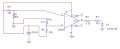
Also, my circuit looks exactly like the one in the picture I've attached. The only difference is that R5 is 330kΩ
That is, if I use a 330kΩ resistor and 470μF capacitor, I'm expecting about 2.5 minutes, but the circuit really ends up taking more than 5 minutes.
Does this have to do with the exponential rise somehow getting slower as Vref is reached?
Also, my circuit looks exactly like the one in the picture I've attached. The only difference is that R5 is 330kΩ
Attachments
-
 40.8 KB Views: 11
Last edited:






