It looks like something is getting warm afther some time.
Can you feel something getting warm (transistors , 555 or opamp) ?
What is the prefix of the 272 (LM,LF or something else) ?
no I can,t tell anything is getting warm the op-amp says(tlc272)
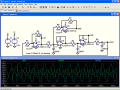
the square wav reads the best and stays consistent but the other two change
the triangle wave goes in and out to a out of control waveform and the sine wave stays out of control.
That's a pretty spiffy sig gen for a homebuilt, Dick - my biggest gripe is that the MAX038 has been out of production for years. They can still be found (Futurlec still has a few) but they're expensive, and Futurlec has a "less than stellar" shipping record; my only order from them took nearly a month to arrive from when it was ordered (but the charge appeared on my credit card within 72 hours).
alright I am going to build the one bertus posted and may try to regulate the voltage to see if that helps to thanks for the help and I will post about it when I am done
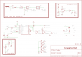
I built the generator and the signal had some distortion in the waveform but I fount a new schematic with a function generator ic.I got the chip ordered and I am going to try to build it when it comes in.there where some pictures of the signal on the scope and they looked pretty good I attached a picture of the schematic.
Another night owl I see. If you go to my blog you can see where I've been working on this project for a while.
The op amp freq response and slew rate is always a problem, the triangle wave should have been very crisp, mine was (but not symmetrical). The symmetry issue is why I'm using the transistor drivers, though it could have been a inverting op amp. The 555 has a problem in that it doesn't go rail to rail, quite, and this translates into a symmetry issue. If you look on my 555 Hysteresis Oscillator article you see why.
When I get around to it I'll probably use a LM324 quad op amp. Very low power, common as dirt, and reliable.
There are two approaches to building a function generator. The classic "Sine-Square" generator of yore....Heathkit et al...used a wien bridge oscillator to generate a sine wave, then ran that through a hard limiter/schmitt trigger to generate a square wave.
Modern function generators start out with a square wave and use an integrator to create a triangle wave, and further integration to create a sine wave. The real advantage of the latter is that you can use a high frequency synthesizer and divide down to get VERY low frequencies...down to millihertz.
That's a pretty spiffy sig gen for a homebuilt, Dick - my biggest gripe is that the MAX038 has been out of production for years. They can still be found (Futurlec still has a few) but they're expensive, and Futurlec has a "less than stellar" shipping record; my only order from them took nearly a month to arrive from when it was ordered (but the charge appeared on my credit card within 72 hours).
Thank you for your kind comment. My wife made the front panel -I envy her talent.
The wave of the future is DSP like the AD5930 rather than analog likeICL0838 and then the MAX038. The price of only $6.38/1k for the AD5930 on the Analog Devices site is telling. I guess we can't go back to the old days.
I have the same complaint about Futurlec. CMOS controllers shipped plugged into white Styrofoam, an order that shipped way too late for me to take it with me on a trip (they subsequently refunded the express shipping charges), and an unauathorzied substitution of parts. Futurlec seems to be good for stuff that's interesting but not important. But there are much worse mail order suppliers out there.
well I got my ic in and built a circuit close to the one I posted.It worked great accept for the hum.my generated frequency was riding on a 60 hz wave.after I built a rejection filter for the 60 hz wave it looks great.
Bertus,
You referenced this thread in another that I was helping someone with.
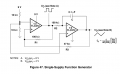
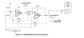
The circuit you posted works, but the amplitudes of the three phases varies quite a bit.

 Facebook
 Google
 GitHub
 Linkedin






 They can still be found (Futurlec still has a few) but they're expensive, and Futurlec has a "less than stellar" shipping record; my only order from them took nearly a month to arrive from when it was ordered (but the charge appeared on my credit card within 72 hours).