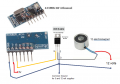
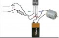
Help be greatly appreciated, Just to wore a basic 4 channel receiver to motor please

Thread Starter

Brinamo

Joined Mar 29, 2021
46
Thanks guys, hmm may scrap and just use the 2 channel with the built in relays, works like a charm. But need to really go smaller. Guess a lost cause here. Much appreciated for he help. Not with all the jargon, Some reading i think. Just thought could go this way, and run one or 2 electro magnets momentary. 1 or 2 seconds off then on 2 or 3 times. Thanks again....
 

Ya’akov

Joined Jan 27, 2019
10,282
The signal pin is digital. Either all on or all off. You can’t use PWM with it.

And the switching speed is too slow for PWM.

One might think the four outputs could be used as input to a four bit digital analog converter. But that wouldn’t work either. That module can only output one channel at a time.

It’s simply the wrong module for your application.
In my testing I've found that in momentary mode I can make any combination of the four data lines go high. So, theoretically, you could transmit four bits at a time, but the data rate would be very slow. I might do it, though, just for fun.
 

Thread Starter

Brinamo

Joined Mar 29, 2021
46
Yaakov. Can i be so bold, if you be so kind how would you go about this please, as part list? know asking a lot but would mean a great deal...
 

Thread Starter

Brinamo

Joined Mar 29, 2021
46
Ok having to try figure the jargon, think what i done was got the wrong mos driver, should just go with a N channel mosfet. As using the latter built in relays, cant do with the click when switching channel.
 

meowsoft

Joined Feb 27, 2021
666
Just throw out that ?#! motors to trash !

Mod Note: Removed inappropriate language.

Wendy.
 
Last edited by a moderator:

Thread Starter

Brinamo

Joined Mar 29, 2021
46
Yes... of course...
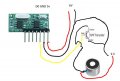
YAY thanks :) HA ok, so, obviously bought the wrong mos driver, should been a mosfet. Looking on youtube, the diagram what was about to post up :) But was unsure of what mosfet to go for. as using standard PP3 9V battery, Thank you...
 

Thread Starter

Brinamo

Joined Mar 29, 2021
46
Ahh ok was just something stumbled upon the PNP,
It could work with a PNP, but it would be wired very differently???
Guess will need to go figure :) Appreciate you input thank you..
 

djsfantasi

Joined Apr 11, 2010
9,237
Ahh ok was just something stumbled upon the PNP,
It could work with a PNP, but it would be wired very differently???
Guess will need to go figure :) Appreciate you input thank you..
Just use an NPN or an N channel MOSFET and wire per your diagram.

With a BJT (NPN) you’ll need a base resistor. And you’ll need to calculate it’s value...

With an N channel MOSFET, for this simple circuit, you can get away without resistors but it will operate better with a 10K resistor between the gate and ground. D0 also goes to the gate.

Plus in any case, you’ll need a diode across the motor terminals with the cathode towards the plus side.

Your diagrams each contain a little piece of truth, but are incorrect in some details.
 
Last edited:

Thread Starter

Brinamo

Joined Mar 29, 2021
46
Ahh ok :) Thanks for your time djsfantasi. Ahh ok yes a cathode prevents electric current back flow..Depending which end you have the grey bit, which if correct is the cathode, other is anode. Now heads hurting ahahah. Will try figure back to google :)
 
Top