Help 12v Adjustable current and voltage

Thread Starter

fouad belkhadem

Joined Jun 28, 2018
26
Dears,

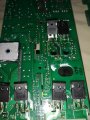
actually im working on HHO Generator Project arduino controlled.

so if any one could help with diagram that could adjust voltage from 10V to 15V max and could limit Current Min 10A max 80A

the board is Arduino uno and i have multiple IRFP460A.(could plug them in parallel) ,large heat sink and fan.

any suggestion about simple schematic diagram?.

thanks a lot for your support.
 

Bordodynov

Joined May 20, 2015
3,431
First, you need to specify which input voltage supply.
Secondly, if you feed off power 220V or 110V and transformerless voltage regulator, then as far as I know, it's taboo on this forum. And it's better for you to buy a ready-made stabilizer or charger.
 

wagnerlip

Joined Mar 31, 2009
2
Hello, first you need to consider that you are building a regulator for 1.2kW power, 15V@80A, considering the VDC needs to be 3 to 5V above the output, so, the DC will be from 18 to 20V.

You do not control this kind of power using linear electronics, except if you want to have a big refrigeration unit to cool down the heat sink when it is supplying 3V @ 80A, what means the regulator will be holding around 15~16V@80A = 1.2kW+, that is outrageous.

A power supply like that needs to be switching and controlled by a specific good switching regulator, high frequency transformer, very low RdsOn MosFET power transistors.

But don't even think to use a microcontroller to control and regulate the transistors, it will never be fast and safe enough. Use a dedicated switching power supply unit. You can, of course, use the microcontroller to setup output voltage and current to the regulators, also, use it to display values on panel.

The primary power section of this 1.3kW power supply, needs to convert 110Vac into +380Vdc via a regular power MosFET flyback unit, voltage doubler and a controller. It is a simple 110Vac through some RFI coils and capacitors, then a 20A bridge rectifier, then a large choke inductor in series with the current, then a couple of large of power MosFET (600V+@10A) to ground, pulse short circuiting the choke with the 180V from the output of the bridge, and a 20A+ double diode charging a couple of 680uF x 450Vdc, presto, large charge of +380V over the capacitors. This above is nothing more than the most common way to build the primary of any large switching power supply, all over the good professional industrial schematics on the internet. Of course, cheap chinese power supplies use a voltage doubler with two electrolytic capacitors and the bridge serving as a semi-sinewave pumping voltage, that is not very smart since it force one capacitor to charge and discharge all the time.

From the +380Vdc you will use the switching controller, four of those 600+VDS@10A power MosFET driving pulses into a nice high frequency switching transformer, with double secondaries, pumping current through 4 large double TO247 diodes, so they could handle the total of 80A nicely. Then the output capacitors. Fortunately you can have easy 25Vdc capacitors around 3300uF to store and filter well this output power, some inductors between the capacitors will be nice to remove the high frequency of the switching.

The feedback from secondary to the switching controller in the primary is done by opto-couplers, and can be monitored by the microcontroller, that can control via a simple DAC the comparison voltage that will control the switching controller. Of course, people use potentiometer to control the output voltage (and current), you can use the microcontroller for such task.

But let me tell you, I work with switching power supplies from 50W to 3kW for years now, fixing, repairing and producing. A 20W power supply is simple to build and make work nicely, but after 50W, it complicates, things get ugly and difficult. A 500W power supply becomes at least dangerous. A power MosFET transistor locking its channel open for one second will cause so much heat accumulate, that its epoxy explodes with a big boom and spit epoxy as a bullet. A bad projected power supply can increase its output voltage in a runaway process that can burn and incinerate everything connected to its output. A 15V power supply can spit 60V or more to the load, frying everything.

It is a nice project, but it requires to go up the ladder or power slowly, learning every step of the way. Start with a 20W power supply, then after playing a lot with and finding all its tricks and failures, step to 50W and so on. Perhaps you can reach 1kW power supply in a couple of years, without doing so much mistakes and failures.

Of course, you want to make the HHO generator now, yesterday perhaps, but one thing at time. First the power supply.

Good luck and be happy in the way - be careful with Hydrogen.

Wagner.
 

Colin55

Joined Aug 27, 2015
519
The famous "free Energy" inventor in Melbourne used a car battery and multiple plates to produce "Brown's Gas" and drove his car all around Melbourne without paying for fuel.
 

Ylli

Joined Nov 13, 2015
1,092
The famous "free Energy" inventor in Melbourne used a car battery and multiple plates to produce "Brown's Gas" and drove his car all around Melbourne without paying for fuel.
We all know there is no such thing as "free energy", "perpetual motion", or "over-unity", right? We know that water is the 'ash' produced by burning hydrogen, and that if you are going to electrolyse water and burn the produced hydrogen, you can't get more out that you put in.
 

ebp

Joined Feb 8, 2018
2,332
"The primary power section of this 1.3kW power supply, needs to convert 110Vac into +380Vdc via a regular power MosFET flyback unit, voltage doubler and a controller. It is a simple 110Vac through some RFI coils and capacitors, then a 20A bridge rectifier, then a large choke inductor in series with the current, then a couple of large of power MosFET (600V+@10A) to ground, pulse short circuiting the choke with the 180V from the output of the bridge, and a 20A+ double diode charging a couple of 680uF x 450Vdc, presto, large charge of +380V over the capacitors. This above is nothing more than the most common way to build the primary of any large switching power supply, all over the good professional industrial schematics on the internet."

You misunderstand the purpose of that part of the circuit. First, it is normally a boost converter, not a flyback. The stage is used for active power factor correction so that the input current waveform is sinusoidal and in phase with the voltage. The circuit must make the instantaneous current directly proportional to the instantaneous input voltage and the average current inversely proportional to the average input voltage, which means it is doing two things that are in conflict with each other. At 1.3 kW, the circuit is not simple to make it work properly. Switchers look simple on paper, but actually making real circuits work properly is a different matter. I've designed active power factor correction circuits at that power level. If I were doing it now I would use interleaved converters.

A 1.2 kW linear power supply can be built. I own one, made by Kepco. The voltage and current are fully adjustable from zero to full output. It is air cooled, but certainly has large heatsinks and large powerful fans. While certain aspects of design of such a supply are simpler than design of a switcher, it is by no means a simple task and a great deal of knowledge would be required.
 

Thread Starter

fouad belkhadem

Joined Jun 28, 2018
26
Thanks All for your support.

@wagnerlip and @ebp.

for power fans and heat sinks i have plenty.

also a i have some rectifiers 220/110V to 48V 50A,a good quality one for use in telecom industry,i have seen some working at full power for more that 3 years ans still working as good as new.

so first i will start with simple 20A 14V duino drived PMW ,is it possible to modify attached diagram to be driven by arduino via optocoupler (PS2701A or any other) and use several SUM110N10-09 (or irfp460a) mosfet in parallel ??

thanks


Attachments

Are you have pcb layout or gerber file please

Thanks All for your support.

@wagnerlip and @ebp.

for power fans and heat sinks i have plenty.

also a i have some rectifiers 220/110V to 48V 50A,a good quality one for use in telecom industry,i have seen some working at full power for more that 3 years ans still working as good as new.

so first i will start with simple 20A 14V duino drived PMW ,is it possible to modify attached diagram to be driven by arduino via optocoupler (PS2701A or any other) and use several SUM110N10-09 (or irfp460a) mosfet in parallel ??

thanks


E
 
Top