HEF4026 and blue LED's

Thread Starter

Fenris

Joined Oct 21, 2007
288
Hi there

I am helping a friend out who is going to be doing a bit of charity work.
For this he needs a prop. I am doing the minor bit of electronics that
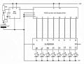
will add a bit of 'bling' to it. I have a 555/4026 circuit driving 8 Red LED's
at the moment on my breadboard. Now the thing is it will actually need
Blue LED's to be accurate and there lies the rub. I know that different
colour LED's have slight differences in current draw etc etc.

The circuit is running without resistors in series with the LED's as per the
diagram I used off the net. But if I use Blue LED's would I need resistors
in line or will I actually need to use a transistor at each output to handle
the LED's in the event that the 4026 can't deal with the demands of the
blue's.

I have found some blue LED's that are not as bright as the sun. Here are the specs could you please advise me as to whether the 4026 could handle them or will I need to insert transistors.

Specifications:
Order Code JA24B: Diffused Blue
Kingbright description: L-53MBD
Viewing angle: 60°
Forward voltage at If=20mA: 4.0V
Forward current max.: 30mA
Reverse voltage max.: 5V
Wavelength @ peak : 430nm
Power dissipation PT: 105mW
Light output min.@ 20mA: 40mcd
Light output typ.@ 20mA: 60mcd

The red LED's I am using are from a cheap diy kit so I have no idea what their ratings are to compare.

I have seen a 4017 chaser circuit that uses transistors at the outputs so know how to set that up if required with the 4026. I think BC547 would do.

regards

Fenris
 

Thread Starter

Fenris

Joined Oct 21, 2007
288
Hi Bertus

I should have said :D It's only 9VDC
I have gone for the next chip up from the one you have shown me as it has 8 inputs/outputs. I've drawn up how i think it needs to be setup. Not sure about pin 9 (GND) or 10 (Common). Have I missed anything?

regards

Fenris
 

Attachments

Thread Starter

Fenris

Joined Oct 21, 2007
288
Hi Bill

Sorry I missed your post. I have indeed already read your tutorials. Yes they helped clarify my understanding but I am basically a complete thicky when it comes to the practical implementation. Working out the maths of VIR to try and work out what I need to use is beyond me. Even though I can use VIR I can't apply it in any practical/useful sense. Believe me it drives me nuts that despite years of tinkering and reading I can't apply and use this information :(

regards

Fenris
 

Audioguru

Joined Dec 20, 2007
11,248
Your Chinese LEDs are not nearly as bright as more modern western LEDs that are 10 times and more brighter. The max allowed current is low so they might not be seen in daylight.

It is good that you have the LEDs connected wrong to the ULN2803 because if it is corrected then the LEDs and the driver would blow up.
You forgot to add current-limiting resistors. The output of the ULN2803 would have tried to put 1A or more into the LEDs that have a max allowed current of only 30mA.

Look at the datasheet for the ULN2803. Its outputs go low, not high.
 

SgtWookie

Joined Jul 17, 2007
22,230
Your Chinese LEDs are not nearly as bright as more modern western LEDs that are 10 times and more brighter. The max allowed current is low so they might not be seen in daylight.
AudioGuru, you're actually pretty knowledgeable about such things - however, pure criticism on selection really isn't helpful. Concentration on specifications would be quite a bit more helpful.

It is good that you have the LEDs connected wrong to the ULN2803 because if it is corrected then the LEDs and the driver would blow up.
No, it is not; if the LEDs were exposed to a Vr of over 5v, it's likely that they were destroyed. Of course, the 5v suggested maximum Vr is just a speculative maximum Vr, but is a reasonable maximum.

You forgot to add current-limiting resistors. The output of the ULN2803 would have tried to put 1A or more into the LEDs that have a max allowed current of only 30mA.

Look at the datasheet for the ULN2803. Its outputs go low, not high.
That's completely true. ULN2803's can only sink current; they cannot source it. Current limiting resistors or active current limiters are a must, unless you wish to destroy your LEDs.

A 9v transistor battery is really not much of a power source; the battery will die quite quickly, and they are rather expensive to buy.

Why don't you explain more about what you're trying to do?
 

Thread Starter

Fenris

Joined Oct 21, 2007
288
Hi Guys

Thanks for your patience :) I can see I have a long way to go........ at 42 I think I may not make it :D

Basically my friend is building a Dr Who prop. In this case a 'worm hole detector' as used in the easter episode 'planet of the dead'. This is a hand held gadget which has been cobbled together-and looks it. It has predominantly blue LED's. Using the 4026 gives a pseudo random effect rather than just a 'chaser' effect which better suits the nature of the prop.

So I would like to be able to drive 8 blue LED's without killing the chips. On a side note I really can't get over how pricey blue ones are :O

a 555, 4026, 2 resistors, 1 capacitor = £1.40
8 blue LED's = £7.20 :O :O

regards

Fenris

PS I always read the data sheets but still some if not all of it goes over my head as can be seen from my attempt to utilise a ULN chip the wrong way. :(
 

Wendy

Joined Mar 24, 2008
23,415
I'm a Whovian, but I don't remember the prop. With this crowd you'll find a lot of us, as well as hard core SciFi readers (one promenent member, whose handle I won't disclose, is a writer). Did you see my "From Four, Twenty" chapter in the LEDs, 555s, Flashers, and Light Chasers? It produces a psudeo random effect.

Maybe you could sketch out a rough draft and scan it?

There was another thread that created the lights and voice from a Darlek, very nicely done.

BTW, what part of the world are you in? Helps when we refer parts and whatnot.
 

Thread Starter

Fenris

Joined Oct 21, 2007
288
Hi Bill

I have been reading your pages again :) I like what I see too. I think audio and light projects seem to be the most popular formats. Well at least with me :D .

A fellow Whovian to boot! Greetings :D BTW It was me, with help on the sound to light part, who did the Dalek voice mod :D They have made it to America, Australia and Israel as well as the UK. It's a bit of a personal success storey ;)

I am currently waiting for the chap who is building the prop to get back to me with details of how the lights need laying out.

Im in Yorkshire. UK

regards

Fenris
 

Wendy

Joined Mar 24, 2008
23,415
OK, I suspect I'll be drowned out on this one, which is good. I'll keep an eye on the thread. BTW, I liked the Darek voice, twas cool.
 

Thread Starter

Fenris

Joined Oct 21, 2007
288
Hi there

Well I am still waiting on my mate to get back to me so I am playing around with ideas using the same circuit. So the theory is adding transistors to the
circuit to act as switches off the CD4026 outputs and they will handle the current draw for the LED's directly. Here's a reconfigured diagram of what I think I need to do to allow the chip to drive the LED's. If I understand the way I have set out the additions it is known as a 'common emitter' which has a slightly more efficient way of working although there are pro's and cons (been reading bills work :D )

So my thing here is what value components would I need (resistors, NPN transistor) to make this work. Battery life isn't a major issue as this is just a prop.

I have tried to work out values but really have no idea what I am doing when trying to do this.

Regards

Fenris
 
Top