Facebook
 Google
 GitHub
 Linkedin
Hi folks,
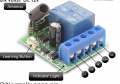
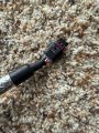
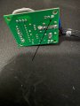
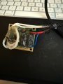
I am trying to replace this circuit board by reverse engineering where the wires are going. I worked out the 3 out of the 4 wires. But this blue wire, I am not sure what the purpose of it is.
I tried to use a multimeter and it gets 0.69v in some cases and 12v in other. It seems to be on same route as the RF antennae?? If that's the case why it is needed? If it's just for power, why couldn't it get it from the positive red wire that is already on the board.
Does anyone know?
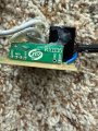
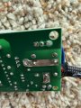
Attachments
-
 996.1 KB Views: 25
 -
 1.8 MB Views: 26