Heating element help

Thread Starter

reza v

Joined Mar 8, 2023
5
I'm not sure if this is the right section for what i'm asking so i'm sorry if i'm doing it wrong but here goes
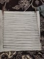
If you look at the picture i provided, you'll see an attempt at making a flat heating element. So the story is i need a heating pad capable of at least 130 degrees Celsius and preferably running at 12v dc. I made this which at the connectors has a resistance of 0.5 ohms. Each of the bridges have a resistance of 2 ohms. The copper wire i wrapped at the ends is temporary. At first i ran it without those and only the ends heated up and faster than the other parts could catch up, hence the burnt bit on the silicone pad. Now that i've wrapped the copper wire, the resistance came down so low that when i connect it to the power supply, it detects a short circuit and cuts the power. What do you reckon is the best way to approach this? Do i have to scrap it and build a maze like design? Or if i reduce the number of bridges it'll work?
My power supply is capable of 30 amps but i'm not very confident that i can reach 130 degrees with it. Any help or input is greatly appreciated.
 

Attachments

Thread Starter

reza v

Joined Mar 8, 2023
5
I must add that the wire is a flat stainless steel 2mm wide heating wire. I ordered nichrome but you don't always get what you order
 

ElectricSpidey

Joined Dec 2, 2017
2,758
If each bridge is equal to 2 ohms and you measure a total of .5 ohms your measurement is off.

If your meter can't zero ohms, press the two probes together and note the reading, then subtract that reading from the element reading.

By my calculations your supply will have to be capable of at least one hundred amps.
 
Last edited:

wayneh

Joined Sep 9, 2010
17,496
In addition to the operating temperature target of 130°C, you need to think about the power consumption. The power needed to maintain the temperature will depend on the rate of heat loss from the elements and the material around them. It could vary from a few amps (maybe 3 amps, 36W), if the elements are well insulated, to hundreds of amps, over 1,000W, if the elements are exposed to ambient air.
 

Pyrex

Joined Feb 16, 2022
247
Hi,
First of all, the total resistance is to be about 2 Ohm/17 bridges = 0.12 Ohm .
I see a problem . Those bridges are simply bended around supplying rods,but this type of connection can't provide reliable contact, especiallly at elevated temperatures. Much better, if they are welded or high temperature soldered.
Second, the copper wire wrapped around supplying rods is not a good solution at elevated temperatures, as copper oxidizes quite intensive and lost the electric contact
 

Thread Starter

reza v

Joined Mar 8, 2023
5
Hi,
First of all, the total resistance is to be about 2 Ohm/17 bridges = 0.12 Ohm .
I see a problem . Those bridges are simply bended around supplying rods,but this type of connection can't provide reliable contact, especiallly at elevated temperatures. Much better, if they are welded or high temperature soldered.
Second, the copper wire wrapped around supplying rods is not a good solution at elevated temperatures, as copper oxidizes quite intensive and lost the electric contact
Don't worry about that this is a test rig it's not permanent. I'm going to weld it. The problem right now is that the resistance is too low and my power supply just thinks it's a short circuit and disconnects the power. What do i do about that?
 

Thread Starter

reza v

Joined Mar 8, 2023
5
If each bridge is equal to 2 ohms and you measure a total of .5 ohms your measurement is off.

If your meter can't zero ohms, press the two probes together and note the reading, then subtract that reading from the element reading.

By my calculations your supply will have to be capable of at least one hundred amps.
Maybe my meter is off. I remeasured everything and it's the same. Maybe it's because the supply wires are the same wire as the bridges.
 

MrAl

Joined Jun 17, 2014
11,389
Don't worry about that this is a test rig it's not permanent. I'm going to weld it. The problem right now is that the resistance is too low and my power supply just thinks it's a short circuit and disconnects the power. What do i do about that?

If the resistance is too low for the power supply to handle and you have enough overhead voltage, you can add a small series resistance to keep the power supply active and still get current though the heating device. The added resistance should be as low as possible in order to keep the power supply happy but not consume too much power and most of all not drop too much voltage that the power supply can not handle.

Typical values might be 0.1 Ohms to maybe 1 Ohms but it depends how much current you need and how much overhead voltage your power supply can actually supply. You might get away with 0.02 Ohms but it depends highly on how the power supply is designed to handle a short.
The wattage of the added resistor will have to be high enough to handle roughly twice the power unless you only need to run for a very short time. Water cooling will also help here with a small vessel of distilled water as long as it does not have to run too long.
 

Sensacell

Joined Jun 19, 2012
3,432
A simple way to generate huge currents at low voltages is to use a transformer and a variac.
Take a power transformer of suitable size with stacked primary and secondary windings, rip the secondary out without ruining the primary.
(microwave oven transformers are good- but NEVER energize it until the secondary has been removed)

Loop one turn through the core, measure the AC voltage on this loop and use this value to calculate the number of turns you need for the desired output voltage.
Wind the heaviest wire you can fit into the core.

Now use this setup with the variac to control the power level.

I have used this method for resistive heater testing with great results.
 
Top