Heart Monitoring with Piezo Contact Mic

Thread Starter

duff650

Joined Mar 15, 2019
38
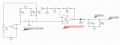
I'm working on a project for a remote heart monitor based on a piezo contact mic and peak detection to identify heartbeats.


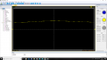
This is my circuit so far, I have the code written for counting the beats and my circuit works, however there is a sizeable background noise. Screenshot of oscilloscope:

upload_2019-3-16_6-26-35.png


upload_2019-3-16_6-3-50.png

Channel 1 (yellow) is output of peak detector, channel 2 (green) is output of amplifier

The peak detector capacitor is all over the place as well, I'm so close to having the system working just need to iron out these problems.

Here is a screenshot of the system in action, piezo pressed to my chest:

upload_2019-3-16_6-19-21.png

There is one spike for the first thump of each heart beat and another for the second thump, making up that "badump" rhythm of the heart

Here is the peak detector:

upload_2019-3-16_6-22-26.png

I'm thinking I'm missing a decoupling capacitor somewhere but I can't figure out where.

Could be the unrealistic gain I've expected from the OP-AMP but I'm unsure.

So to sum up I need help reducing noise and if possible I need a better Vref for the comparator, I currently have it set at just over 2.5v but obviously if I can make this dynamic to allow for quieter or louder heartbeats that would be perfect.

Any input is greatly appreciated!
 

Attachments

ericgibbs

Joined Jan 29, 2010
18,766
hi duff,
Your circuit diagram shows no decoupling on the 5V power rail.
A 100uF and 100nF cap is advisable.
E

What is the source of the 5V.?
 

Thread Starter

duff650

Joined Mar 15, 2019
38
hi duff,
Your circuit diagram shows no decoupling on the 5V power rail.
A 100uF and 100nF cap is advisable.
E

What is the source of the 5V.?
where would I put them?

Using a 9v battery divided to ~4.9V.

In terms of the peak detector am I correct in saying the discharge time should be 5 x C x R?

If so that is not what is happening here, discharge time should be a lot longer than it actually is as you can see from the scope. I want it to be roughly 0.2 seconds.

I need to refine the process to allow for noise etc
 

Alec_t

Joined Sep 17, 2013
14,280
With such high input impedances, noise pickup is very likely.
Is your circuit inside a metal screening enclosure? Are all signal-carrying conductors screened?
 

Thread Starter

duff650

Joined Mar 15, 2019
38
hi duff.
The decoupling should be on the project board, connected between +5V and 0v/Common.
How are you dividing the 9Vbty down to +5v.??
E
Please check this LTSpice circuit is correct compared to yours
Added a 10k resistor before the diode and a 100uF capacitor instead of the 10uF after the diode, everything else should be the same
 

ericgibbs

Joined Jan 29, 2010
18,766
OK,
Got that added.
Please post a scope image of the heart beat output of the piezo, if your scope can see such low level signals.
E
 

Thread Starter

duff650

Joined Mar 15, 2019
38
With such high input impedances, noise pickup is very likely.
Is your circuit inside a metal screening enclosure? Are all signal-carrying conductors screened?
breadboarded at the moment, piezo is in a bit of plastic just now. Full circuit attached, includes transmitter. The unit on the left will be contained in plastic casing 30mm in diameter with the peak detection circuit and a basic program on an arduino nano to count heartrate and a thermometer for core temperature, and then transmitted
 

Attachments

ericgibbs

Joined Jan 29, 2010
18,766
hi duff,
Looking at the project photo, that very loose layout is going to give lots of noise problems, especially around the piezo inputs.
Who designed the amplifier circuits.?
E
 

Thread Starter

duff650

Joined Mar 15, 2019
38
hi duff,
Looking at the project photo, that very loose layout is going to give lots of noise problems, especially around the piezo inputs.
Who designed the amplifier circuits.?
E
upload_2019-3-16_10-54-44.png

I did, do you think a transistor based pickup before the amplifier will help??
 

ericgibbs

Joined Jan 29, 2010
18,766
hi,
I would use another low noise OPA preamp between the piezo and the following OPA's
Looking at that image, is the amplitude approx 50mV and how many beats per second, its hard to read.?
I would also change the design of that 1st OPA in your *1000 circuit.
The time constants for the peak detector are too long.
E
 

Thread Starter

duff650

Joined Mar 15, 2019
38
I’ve refined the circuit everythings working as expected now, decoupled the rails etc thank you for your input @ericgibbs! I just need the piezo to pickup lower frequencies now if thats possible. I have 9 Mohm in parallel with the piezo input and its very sensitive to higher frequency sounds such as music and my voice, I’m looking for the same kind of sensitivity in the 20-150Hz range if anyone is able to guide me, I can post circuit diagrams and oscilloscope outputs if required! My active band pass works but I have to add a lot of gain after to get a consistent reading for the BPM. Cheers!
 

Thread Starter

duff650

Joined Mar 15, 2019
38
upload_2019-3-20_12-9-54.png

Here is the output of the OP-AMP as is right now, this is pressed into my chest quite heavily.

And the circuit:

upload_2019-3-20_12-22-38.png


Its an LM324 same as last time.

Looking into better OP-AMPS based on your recommendations earlier
 

Attachments

ericgibbs

Joined Jan 29, 2010
18,766
hi duff,
Please confirm that R4 and R5 are 1meg and 100R, thats a gain setting of 10,000.!!!

E

EDIT:
Also is the TL OPA supply =5v.?
 
Last edited:

Thread Starter

duff650

Joined Mar 15, 2019
38
hi duff,
Please confirm that R4 and R5 are 1meg and 100R, thats a gain setting of 10,000.!!!

E
My bad R5 is 10k!!!:eek: that's default CircuitLab settings I missed sorry

My problem is that I'm not sure if the piezo has enough input impedance to be capable of picking up the low frequencies, I've been researching and I'm thinking a charge amplifier might be better??
 
Top