Headphone Amplifier

Thread Starter

ankur3000

Joined Dec 28, 2010
9
Hello forum,
I have decided to make a simple, low power headphone amp (as a school project). I have found the attached circuit diagram from the following source: http://electronics-diy.com/4x4.php .
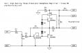
headphone_amp.jpg

However, before actually making the amp, I want to make sure the circuit is correct and does what it claims. So, could you guys please have a look and tell me if it would work and are there any improvements/additions that I could make for a better amp/project.

**Additional Note: Before anyone shouts at me for being too lazy and telling me to check the circuit myself, I just want to clarify that since this is my first electronics project, I want to make sure that the design is actually correct before making it, so that, if the results are not as expected, I will know that its purely my mistake.

Thanks
 

kubeek

Joined Sep 20, 2005
5,796
First, there are no values in the schematic, second, one gain amplifier and a complimentary output won´t bee to nice to listen to.

This is just a bit more complex and should have much better sound. What power sources do you have available / want to use?
 

KJ6EAD

Joined Apr 30, 2011
1,581
Last edited:

Thread Starter

ankur3000

Joined Dec 28, 2010
9
Thanks for all the great feedback,

Here are the component values (from the site):

Part's List:
R1 - 100K
R2 - 330
R3 - 100
R4 - 22 (2 - 4.5V)
R4 - 100 (5 - 12V)
C1 - 4.7uF
C2 - 4.7uF
C3 - 100 - 1000uF
C4 - 220uF

P1 - 100K
D1, D2 - 1N4148
Q1, Q2 - BC549
Q3 - BC559

The power source will be a simple regulated DC power supply.

I forgot to specify but the professor has specified that our design must use a BJT for the amplification (he is o.k. with us using designs from the internet).

Another question I have is regarding the impedance of the headphone, do you think this design would work with standard off-the-shelf headphones (normally 32 ohms), and will your suggested design work with 32-ohm headphones.
 

KJ6EAD

Joined Apr 30, 2011
1,581
Unfortunately the CMoy design violates the OP's discrete amp requirement. The Collinson design description claims that it will drive loads ≥8Ω.
 

Hi-Z

Joined Jul 31, 2011
158
I personally wouldn't contemplate a headphone amplifier which operates in class AB. The only advantage of AB is that it's more efficient than class A - in all other aspects it's inferior (especially in the area of crossover distortion), even if a lot of effort is put into the design (which isn't evident here, by the way). A headphone amp doesn't need to push out much in the way of power (compared with driving loudspeakers), so class A is appropriate.

Mind you, it's not clear that any given class AB design will actually get beyond class A - it's all a question of standing current, headphone impedance and sensitivity... I have to go now, but I'll come back to the subject tomorrow.
 

KJ6EAD

Joined Apr 30, 2011
1,581
I like the idea of making it class A, especially now that I know it's not going to run on batteries. Here's Rod Elliott's Class A headphone amplifier design:
http://sound.westhost.com/project70.htm.

This is the larger project it's based on:
http://sound.westhost.com/project36.htm.

This is Rod's article about Class A more generally:
http://sound.westhost.com/class-a.htm#class-a.

Finally, this is the order page for a bare PCB for the above amplifier:
http://sound.westhost.com/pcb/pricelist.html.
 

Hi-Z

Joined Jul 31, 2011
158
I was in a hurry yesterday, and I hadn't fully appreciated the fact that the main reason for this was a school project.

Now the fact is, it's easy to design a very simple class A headphone amplifier, and it would sound good too. It wouldn't be very efficient, but that's not a concern here. However, I couldn't find any class A designs on the 'net which were as simple as the design you're contemplating. So, I had another look at your circuit.

Most class AB designs have to be quite (or very) sophisticated and complex to work well. However, this one is quite clever, and, apart from some (fairly severe) compromises, does offer a neat solution - particularly if you're after efficiency (which you're not) and simplicity (which you are). Sound quality is claimed to be good (though it certainly won't be hi-fi), so you're probably OK.

I would think the design is pretty foolproof - the only possible problem might be self-oscillation in the output transistors. This would be difficult to detect/diagnose, particularly as the output transistors are off when there's no signal. However, you can guard against this by adding a 56 ohm resistor in series with each of Q2 and Q3's bases - these should be physically as close to the transistor as possible. (They're perorming the function of a "base stopper".)

Anyway, good luck with your project!
 

Hi-Z

Joined Jul 31, 2011
158
PS: I ought to have pointed out that the design is fairly foolproof, BUT do realise that the output transistors are meant to be off when there's no signal, and this would be dependent on the fact that the voltage across the two diodes is less than that required to turn on Q2/Q3. If this isn't the case, then you'll notice the quiescent current is significantly greater than indicated by the author. This may be down to choice of diode - anyway, it's just something to look out for.
 
Top