 Facebook
 Google
 GitHub
 Linkedin
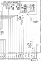
Hi folks, I'm trying to troubleshoot an issue in a synthesizer I have, an early 80s synthesizer from Roland called RS-09. I'm just starting to study logic and am perplexed by what's going on. In this synthesizer, a 4013 is being used as a frequency divider to divide or not divide a trigger signal from a master oscillator based on whether the user has selected a feature called "Octave down" via a switch. The output Q of the 4013 then passes to a "top octave generator" that uses it to generate the 12 notes of a chromatic scale from which all the other notes are made. Right now it is only working in "Octave down" mode; without "Octave down" selected, all keys just produce noise. Here's a closeup of this part of the schematic:

The 4013 is set up so that the "high" voltage is 0V and the "low" voltage is -10V. When the "Octave down" is selected and the 4013 is supposed to divide, ~-10V is connected to SET2 (pin 8) via the 15kohm resistor; when "Octave down" is not selected, ~0V is connected to that path.
In Octave down mode, that -10V is also able to pass through the diode D206 to RESET2 (pin 10) (less 0.6V from the diode drop of course) and with reset and set held in the low state, the flip flop is in clocked mode, responding to the trigger signal from the master oscillator. This seems to be working just fine. With Q/ connected to D as it is, the flip flop also "binary divides" and Q outputs a square wave at 1/2 the frequency of the trigger.
My problem is that I don't understand what's supposed to be happening when "Octave up" is not selected. I don't see how it could possibly work, and it doesn't. This is what my understanding is, but something must be wrong:
The ~0V at SET2 holds it in the high state but cannot pass through D206 to RESET2, leaving the reset open to receiving its "instructions" from the oscillator (direct mode). The trigger oscillator starts out oscillating between +5 and -10V but the diode clamps it at 0V to cut off the positive portion and is then sent to RESET2. But with the set held high, the only possible outcomes for Q are the high state when the oscillator is at its low point sending ~-10V to Reset, when Q is high and Q/ is 0, and the "disallowed state" of both Set and Reset being high, leading to both Q and Q/ being high, when the oscillator is at its high point. Therefore, Q just sends out a constant "high voltage" (0V in this case) with a little bit of noise. That is what I'd expect and what I'm seeing it do. My measurements confirm that this is what is happening.

How is this supposed to work? Something is clearly wrong both in my interpretation of how it should work and in the way the circuit is actually working, but I've looked it over so many times and still can't figure it out.
Your help is very much appreciated!
The 4013 is set up so that the "high" voltage is 0V and the "low" voltage is -10V. When the "Octave down" is selected and the 4013 is supposed to divide, ~-10V is connected to SET2 (pin 8) via the 15kohm resistor; when "Octave down" is not selected, ~0V is connected to that path.
In Octave down mode, that -10V is also able to pass through the diode D206 to RESET2 (pin 10) (less 0.6V from the diode drop of course) and with reset and set held in the low state, the flip flop is in clocked mode, responding to the trigger signal from the master oscillator. This seems to be working just fine. With Q/ connected to D as it is, the flip flop also "binary divides" and Q outputs a square wave at 1/2 the frequency of the trigger.
My problem is that I don't understand what's supposed to be happening when "Octave up" is not selected. I don't see how it could possibly work, and it doesn't. This is what my understanding is, but something must be wrong:
The ~0V at SET2 holds it in the high state but cannot pass through D206 to RESET2, leaving the reset open to receiving its "instructions" from the oscillator (direct mode). The trigger oscillator starts out oscillating between +5 and -10V but the diode clamps it at 0V to cut off the positive portion and is then sent to RESET2. But with the set held high, the only possible outcomes for Q are the high state when the oscillator is at its low point sending ~-10V to Reset, when Q is high and Q/ is 0, and the "disallowed state" of both Set and Reset being high, leading to both Q and Q/ being high, when the oscillator is at its high point. Therefore, Q just sends out a constant "high voltage" (0V in this case) with a little bit of noise. That is what I'd expect and what I'm seeing it do. My measurements confirm that this is what is happening.
How is this supposed to work? Something is clearly wrong both in my interpretation of how it should work and in the way the circuit is actually working, but I've looked it over so many times and still can't figure it out.
Your help is very much appreciated!
Attachments
-
 52.3 KB Views: 3
Last edited:


