H Bridge not working, no idea why

Thread Starter

swamptrooper

Joined May 21, 2019
6
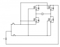
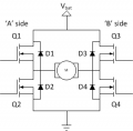
So I've been building a simple H bridge circuit with a motor and IRF540s (pictured) and can't figure out why it keeps failing. It seems when I hook up ground to the drains of MOSFETs Q2 and Q4, my button presses have no impact. However, hooking up just one path (Q4 or Q2) of the H Bridge makes it so that the associated button spins the motor in the respective direction. This works with both paths individually but not simultaneously. I am stumped as to why this is happening.
 

Attachments

Thread Starter

swamptrooper

Joined May 21, 2019
6
Ah. It seems my explanation wasn't clear enough. I set up my H Bridge and press only the button to get the motor to spin clockwise. It does not, unless the ground connected to Q2 is removed entirely. Similarly if I press only the button to get it to spin clockwise, I have the same error.
 

DickCappels

Joined Aug 21, 2008
10,661
You can only have two MOSFETs on at a time.

One of the valid combinations are Q1 and Q4 on with Q1 and Q3 off and the other valid combination is the opposite:Q1 and Q4 off with Q1 and Q3 on.

With other combinations either nothing will happen or a lot of potentially destructive current will flow.
 

Dodgydave

Joined Jun 22, 2012
11,395
You need to link Q1 and Q4 gates together with a 1K pull down resistor, and the same with Q2, Q3 gates, then feed a positive signal into Q1 pair only, the motor will spin one way, and then try Q2 pair only, it will spin in reverse.

Better still use Pfets for Q1, Q3 ..and link Q1, Q2 gates and Q3, Q4.
 
Last edited:

dendad

Joined Feb 20, 2016
4,637
It would help if you put the full circuit of your setup here. What you have published is only part of it, and that does not work.
If you really want help, please help us by giving us enough info to work from.
 

Daniel Sala

Joined May 28, 2015
65
Hi,

Your circuit is not the same as the schematic in post #1. If the schematic you just posted is the actual circuit you are using, Crutschow answered what is wrong with it in the same thread you posted with a similar name.
 

dendad

Joined Feb 20, 2016
4,637
Thanks for the circuit.
The bad news is it is quite wrong.
Here is one that uses P channel FETs in the top positions..
FET-H-Bridge1.jpg
If you want to use all N channel FETs, the gates need a floating supply to raise them above the power supply voltage.
There are commercial driver chips that have a built in charge pump to generate this gate supply.

Look at this data sheet..
https://www.infineon.com/dgdl/ir2110.pdf?fileId=5546d462533600a4015355c80333167e

Or like this one, but I have not used it myself, so cannot comment on how it works.
33883 H Bridge.png

And it really is not a good idea to keep starting new threads because you do not like the answers you get on the other ones.
You presumably came here for help, and we are happy to do that. But why do you ignore the help when offered? The circuits you are posting are just plain wrong, and you have been pointed in the correct direction. Try following the help and see how that goes.
 
Last edited:
Top