GPS NMEA antenna aiming tracker.

Thread Starter

camerart

Joined Feb 25, 2013
3,842
hi C,
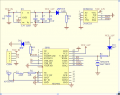
Try changing the 4 to a 5 in this program line
If str1(5) <> "G" Then Goto etm

This should allow only the $GPGGA message thru and block all other
$GPG.. S,,, T,, B etc messages

At the moment all messages with 'G' in the 4th position are being accepted and the TXD cannot keep a lock.

Let me know the result.
E
Hi E,

Again 1X sentence, all (15) $GPGGA apart from a GSA truncated one.

C.
 

ericgibbs

Joined Jan 29, 2010
21,460
Hi E,

Again 1X sentence, all (15) $GPGGA apart from a GSA truncated one.

C.
hi,
I dont understand what you are saying.. all (15) $GPGGA apart from a GSA truncated one.

I think the quickest way is if I buy a Neo6 module same version as yours, I cannot fault the program or PIC on my setup here.

Please confirm the Neo model type Version etc... Price and Supplier, I will order a couple of modules.

Eric
 

Thread Starter

camerart

Joined Feb 25, 2013
3,842
hi,
I dont understand what you are saying.. all (15) $GPGGA apart from a GSA truncated one.

I think the quickest way is if I buy a Neo6 module same version as yours, I cannot fault the program or PIC on my setup here.

Please confirm the Neo model type Version etc... Price and Supplier, I will order a couple of modules.

Eric
Hi Eric,

Sorry!

From 15 tests: Switch on, wait for GPS to warm up, then switch in GPS, they were all $GPGGA apart from one $GPGSA which was a truncated message.

I have spare NEO-6 GPS modules, I'll post one to you.

C.
 

Thread Starter

camerart

Joined Feb 25, 2013
3,842
Hi Eric,

Re: your PM.

The output of the GPS is 3.3V at the PIC RX pin and 5V at the PIC TX pin and I suspect the GPS should either be set to 5V or pass through a MAX 232. As you say, this might be the problem. I'll investigate.

C.
 

Thread Starter

camerart

Joined Feb 25, 2013
3,842
Hi Eric,

On my circuit is a disconnected Max232. I re-connected it, to get the voltage GPS voltage from 3.6V to 5V, and got interference on the putty screen. I think this is why it was disconnected.

I don't think the NE0-6 can output 5V.

Today I used the 'other' program today to collect data, which makes me think it might not be the voltage that is stalling your program.

I've posted a GPS module to you, so you can connect it to your circuit. Looking forward to seeing the results.

C.
 

THE_RB

Joined Feb 11, 2008
5,438
The GPS serial output at 0-3.3v will work fine with the PIC RX USART 0-5v input pin, all they normally need is an external 22k pullup resistor to +5v on that RX pin. :)
 

ericgibbs

Joined Jan 29, 2010
21,460
hi C,
Your mailed Neo6m GPS module received OK.
I have searched the web and the attached data is what I believe the unit to be, please confirm before I warm up my 100Watt solder iron.:eek:

I have examined the GPS pcb and it has 3.3Vreg on board, as shown on the attached circuit diagram.

Also this text is from the eBay web page.
I see that it says 3v to 5v for Vcc input, I am wondering why you were only using 3V.???
Eric
Features:
ublox/u-blox NEO-6M GPS module with antenna and build-in EEPROM
This module is compatible with APM2 and APM2.5,
and EEPROM can save all your configuration data.
The battery Model is MS621FE,Need to welding
Battery not included.
Interface: RS232 TTL
Power: 3-5V
Baudrate default:9600bps

Specifications:
Antenna size: 25 x 25mm
Module size: 25 x 35mm
Install hole dia.: 3mm
Net weight:19g
Package weight:29g

Pacakge content:
1x Ublox NEO-6M APM2 GPS Module
 

Attachments

Thread Starter

camerart

Joined Feb 25, 2013
3,842
hi C,
Your mailed Neo6m GPS module received OK.
I have searched the web and the attached data is what I believe the unit to be, please confirm before I warm up my 100Watt solder iron.:eek:

I have examined the GPS pcb and it has 3.3Vreg on board, as shown on the attached circuit diagram.

Also this text is from the eBay web page.
I see that it says 3v to 5v for Vcc input, I am wondering why you were only using 3V.???
Eric
Features:
ublox/u-blox NEO-6M GPS module with antenna and build-in EEPROM
This module is compatible with APM2 and APM2.5,
and EEPROM can save all your configuration data.
The battery Model is MS621FE,Need to welding
Battery not included.
Interface: RS232 TTL
Power: 3-5V
Baudrate default:9600bps

Specifications:
Antenna size: 25 x 25mm
Module size: 25 x 35mm
Install hole dia.: 3mm
Net weight:19g
Package weight:29g

Pacakge content:
1x Ublox NEO-6M APM2 GPS Module
Hi Eric,

Received ok, good. Warm up the 100 watter, it's the correct module:)

Must be crossed wires somewhere (Not literally), as my VCC is 5v

I think the battery they refer to has already been welded in. Top right of the module.

I haven't found out how to get more than 3.3V from the TX yet, but as mentioned by Roman, 3.3V (with pull up 22K) is enough to work on the PIC.

C.
 

THE_RB

Joined Feb 11, 2008
5,438
I use my 3.3v TTL output GPS straight into a PIC USART RX input all the time.

With the 22k pullup resistor it works fine, the "3.3v" HI level goes up to about 4v, which registers as HI on the PIC USART RX input which is a ST input (usually needs >3.5v to go HI).

On some PICs the ST input pins register Hi as low as 3v, so the pullup resistor might not be needed. Your mileage may vary. ;)
 

Thread Starter

camerart

Joined Feb 25, 2013
3,842
I use my 3.3v TTL output GPS straight into a PIC USART RX input all the time.

With the 22k pullup resistor it works fine, the "3.3v" HI level goes up to about 4v, which registers as HI on the PIC USART RX input which is a ST input (usually needs >3.5v to go HI).

On some PICs the ST input pins register Hi as low as 3v, so the pullup resistor might not be needed. Your mileage may vary. ;)
Hi Roman,

The USARTs on my PICs always seem to be working, I added the 22K resistor and the HI level still seems to be 3.3V. I'm not sure if it has made the switching more reliable though.

C
 

ericgibbs

Joined Jan 29, 2010
21,460
Hi Roman,

The USARTs on my PICs always seem to be working, I added the 22K resistor and the HI level still seems to be 3.3V. I'm not sure if it has made the switching more reliable though.

C
hi,
I tried 22K , it had no effect on the 3v3 TTL level, however the PIC shows no problems with a 3.3v RXD signal.

E
 

THE_RB

Joined Feb 11, 2008
5,438
Thanks for the info, the GPS module might be different to the one I remember, it was a Ublox 6 I think.

Anyway if it's working it's working. :D
 

ericgibbs

Joined Jan 29, 2010
21,460
hi C,
This is a stripped down version of the CamLog4P1, it works OK with the Neo6 module.
Only the $GPGGA message is sent from the PIC to the external PC via RS232.

Just in time for your weekend logging.:rolleyes:

Eric

Also a txt log from today of the Neo6 to PC, the weather is overcast so the satellite lock is not so good, on my bench.
 

Attachments

Thread Starter

camerart

Joined Feb 25, 2013
3,842
hi C,
This is a stripped down version of the CamLog4P1, it works OK with the Neo6 module.
Only the $GPGGA message is sent from the PIC to the external PC via RS232.

Just in time for your weekend logging.:rolleyes:

Eric

Also a txt log from today of the Neo6 to PC, the weather is overcast so the satellite lock is not so good, on my bench.
Hi E,

Working perfectly, and rendered my old program obsolete.

Thanks, C
 

Thread Starter

camerart

Joined Feb 25, 2013
3,842
I have been trying to get an LEA-6H-0-002 module to work in putty. I've tried 'all' of the baud rates, and other settings, but the best I've had is: see attached putty screen. With different settings, obviously the screen looked different e, g, at 115200: See attached

EDIT: Since posting, I've read that the LEA-6H can be configured for either UBLOX system or NMEA. I don't want to change the settings, so I'll stick to the NEO-6M.

Any ideas? C
 

Attachments

Last edited:

Thread Starter

camerart

Joined Feb 25, 2013
3,842
That could just be a baudrate mismatch.

Do you have a 'scope or some way to see the serial output waveform?
Hi Roman,

I have a scope, and can see parts of the square wave.

I think the LEA6-H has been configured to the UBX system, for use with Ardupilot etc, and I'm reluctant to alter is for safety reasons.

Here is the PDF for information: http://www.u-blox.com/images/downloads/Product_Docs/u-blox6_ReceiverDescriptionProtocolSpec_%28GPS.G6-SW-10018%29.pdf

As you can see it's quite involved:eek: and it's only for comparison with the NEA-6M

C
 
Top