GPS NMEA antenna aiming tracker.

Thread Starter

camerart

Joined Feb 25, 2013
3,840
hi C,
We can dump the 5 lines of Initialise if you dont need it.??

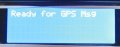
I am puzzled by the actual GPS messages shown in that image taken from the Putty screen.

There is no time or coordinate data in the GPS messages.???

E
Hi E,

This was done indoors to show the initialisation, mainly. I have to go outside to get it to 'see' satellites, then I can bring it in.

As we only need the $GPGGA sentence, could you 'dump' all the rest?

Cheers, Eric.
 

ericgibbs

Joined Jan 29, 2010
21,459
hi,
I have already tried the Ublox initialise messages into the program, it reads them OK, it does not lock up the program
It tries to use them to calc the Range and Azimuth which gives a silly result, but thats just a matter of detecting the $GPTXT header part and ignoring those headers in the final program,

When you power up your project, try powering up the Ublox first, then power up the PIC, lets see what you get.
Its possible that the Ublox is putting out an 'odd' character on power up.
E

BTW: Let me know which $GG headers are going to be used, I use the $GPGGA at present.
 

Thread Starter

camerart

Joined Feb 25, 2013
3,840
hi,
I have already tried the Ublox initialise messages into the program, it reads them OK, it does not lock up the program
It tries to use them to calc the Range and Azimuth which gives a silly result, but thats just a matter of detecting the $GPTXT header part and ignoring those headers in the final program,

When you power up your project, try powering up the Ublox first, then power up the PIC, lets see what you get.
Its possible that the Ublox is putting out an 'odd' character on power up.
E

BTW: Let me know which $GG headers are going to be used, I use the $GPGGA at present.
Hi E,

I have added the the MCLR pull up/down. Would this serve as a PIC hold while GPS powers up?

$GPGGA is correct and the only one we need.

C
 

ericgibbs

Joined Jan 29, 2010
21,459
Hi E,

I have added the the MCLR pull up/down. Would this serve as a PIC hold while GPS powers up?

$GPGGA is correct and the only one we need.

C
Hi,
You could add a capacitor from pin #1 to 0V in order to extend the Reset period, but I would add a 1N4148 across the pull up resistor,, anode to pin1, cathode to +5V, this would allow a larger value of capacitor.

The diode would act as a discharge path for the Cap when switching Off.

I have modified the program for the UART, it appears that the Oshonsoft Basic command 'Enable High' does not always enable the RCIF interrupt, so I have added register control, which works OK to clear garbage,

E
 

Thread Starter

camerart

Joined Feb 25, 2013
3,840
Hi,
You could add a capacitor from pin #1 to 0V in order to extend the Reset period, but I would add a 1N4148 across the pull up resistor,, anode to pin1, cathode to +5V, this would allow a larger value of capacitor.

The diode would act as a discharge path for the Cap when switching Off.

I have modified the program for the UART, it appears that the Oshonsoft Basic command 'Enable High' does not always enable the RCIF interrupt, so I have added register control, which works OK to clear garbage,

E
Hi E,

The switch I added is a press to contact button, when pressed, shorts pin #1 to ground is this correct?

C
 

ericgibbs

Joined Jan 29, 2010
21,459
hi C,
This is a working program for writing into a 18F PIC.

The RX2LCD4P.txt is ready for a PIC, I have also attached the Hex file for you to prog a PIC.

It works OK, the Ublox initialise msg will show 'Not a GPGG msg' on the LCD.

Any nonsense characters will show '!' on the LCD, this is just a flag for your debugging tests.

Upon receiving a valid GPGG msg the LCD will calculate from the GPS coordinates and display the Range and Azimuth of the Remote point on the LCD, the Alt-itude is whats sent in the GPS string NOT the remotes!.

The Keypad also shows '0 thru F' on the LCD in real time.

NOTE:

for testing at my location I have used 50N 2W as my Local point
latrad1 = 50 / 57.295779
lonrad1 = 2 / 57.295779
latcos1 = Cos(latrad1)


You will have to add to the program so that you can load/enter the Local coords point to suit your position.

Good Luck!:rolleyes:
Eric

EDIT:
Change in the Basic program listing the two Local Coordinates to move the Reference to your required location.
The Coordinates must be in Degrees and Decimal degrees
example: 51.12333== 51Deg 07Min 24Sec

Rich (BB code):
rng = 6371
rad = 57.295779

latrad1 = 50 / 57.295779 ' the divisor changes the degrees to radians.
lonrad1 = 2 / 57.295779
latcos1 = Cos(latrad1)

Lcdcmdout LcdLine1Home
Lcdout "Ready for GPS Msg"
Enable High  'peripherals now initialised , so Enable Intr
msgflg = 0

PORTB = 0x0f
LATB = 0x0f
 

Attachments

Last edited:

THE_RB

Joined Feb 11, 2008
5,438
...
This was done indoors to show the initialisation, mainly. I have to go outside to get it to 'see' satellites, then I can bring it in.

As we only need the $GPGGA sentence, could you 'dump' all the rest?
...
That output is normal when the GPS has not locked. There will be no chars between the field delimiting commas.

You may not have to go outside, just leave it running for 10 or 20 minutes, it should slowly lock to more satellites over time. :)

You don't need to "dump" other data, you just need to detect the GGA tag, and grab the text bytes after it. Then separate the data into fields based on the number of commas. I assume that is what Eric's code does anyway.


...
My concern is the additional program space/time load when the OP starts having to detect the 'rotatory encoded' disc and PWM motor drives in the X, Y, and Z axis!
Sorry Eric if I keep butting in suggesting redundant things. :) You're obviously putting in a lot of effort here and I have not looked at your code etc.

Regarding the other tasks, isn't the base station (this device) stationary? So you only have to read the GPS once, to get the base station lat/long/ele, then it has all the time in the world to do calcs and drive motors etc after that.

Or am I misunderstanding the operation?
 

ericgibbs

Joined Jan 29, 2010
21,459
Sorry Eric if I keep butting in suggesting redundant things. :) You're obviously putting in a lot of effort here and I have not looked at your code etc.
Hi Roman,
I never see your input as butting in, as always, I see it as cooperation in putting our heads together and giving the OP our best advice.

Regarding the other tasks, isn't the base station (this device) stationary? So you only have to read the GPS once, to get the base station lat/long/ele, then it has all the time in the world to do calcs and drive motors etc after that.
Or am I misunderstanding the operation?
As I understand the project, the OP requires it to operate in two modes.

1. The Base [Local] station needs to be relocatable and have a guided Yagi aerial that can receive 'relayed' GPS data from a Remote moving transmitter.
The Remote has its own GPS receiver on board and it then transmits that GPS position data to the Base station [local] Yagi receiver.

The Remote relay transmitter can be some distance from the Base receiver, so the Base station high gain Yagi needs to be pointed at the Remote as it moves around.

From the Remotes GPS position data and the Base station GPS data the program calculates the Range and Azimuth of the Remote relative to the Base and points the Yagi at the Remote.


2. The OP also wants to track Earth orbiting satellites as they pass over head. Displaying the received Azimuth and Altitude data.

Eric
 

Thread Starter

camerart

Joined Feb 25, 2013
3,840
Hi Roman,
I never see your input as butting in, as always, I see it as cooperation in putting our heads together and giving the OP our best advice.

As I understand the project, the OP requires it to operate in two modes.

1. The Base [Local] station needs to be relocatable and have a guided Yagi aerial that can receive 'relayed' GPS data from a Remote moving transmitter.
The Remote has its own GPS receiver on board and it then transmits that GPS position data to the Base station [local] Yagi receiver.

The Remote relay transmitter can be some distance from the Base receiver, so the Base station high gain Yagi needs to be pointed at the Remote as it moves around.

From the Remotes GPS position data and the Base station GPS data the program calculates the Range and Azimuth of the Remote relative to the Base and points the Yagi at the Remote.


2. The OP also wants to track Earth orbiting satellites as they pass over head. Displaying the received Azimuth and Altitude data.

Eric
Hi,

Just to clarify.

The purpose of the tracker is to aim antennas at remote objects, for better reception of signals e,g, video, control and communication, by using the location data sent from the remote object.

Camerart.
 

THE_RB

Joined Feb 11, 2008
5,438
Thanks guys i got it now. :) I missed that point about the remote object transmitting coord data to the base station.

That does open up some options. For instance your remote object can format and reduce the data before transmitting, which may alleviate some data parsing by the base station receiver.

And if only sending a few coord numbers (lat/long/ele) there will be less bytes to send, so the baudrate can be a lot slower, giving the base station more time between each received byte interrupt. That improves the timeslice situation re fitting in all the real time motor control stuff etc.

However I would still be temtped to use one PIC just for the 2-axis motor control, and one PIC for the data processing, math, display and user interface.
:)
 

Thread Starter

camerart

Joined Feb 25, 2013
3,840
Thanks guys i got it now. :) I missed that point about the remote object transmitting coord data to the base station.

That does open up some options. For instance your remote object can format and reduce the data before transmitting, which may alleviate some data parsing by the base station receiver.

And if only sending a few coord numbers (lat/long/ele) there will be less bytes to send, so the baudrate can be a lot slower, giving the base station more time between each received byte interrupt. That improves the timeslice situation re fitting in all the real time motor control stuff etc.

However I would still be temtped to use one PIC just for the 2-axis motor control, and one PIC for the data processing, math, display and user interface.
:)
Hi Roman,

If we treat all remote object data the same, then filter out the relevant data we need, this is more straight forward.

A second PIC for driving motors is possible, if needed.

C.
 

ericgibbs

Joined Jan 29, 2010
21,459
hi C,
Following on Roman's point, is the Remote 'system' a propriety unit or it something you intend to design and build yourself.?? [ obviously the GPS rxr part will be a Ublox, I guess].

Can you confirm on the present tests you are doing, that the Ublox is sending GPS position data at a one second rate.??
E

EDIT:
Looking online there are a number versions of the Neo-6m module, could you confirm which version you are using.?
With a supplier, price etc.
 
Last edited:

Thread Starter

camerart

Joined Feb 25, 2013
3,840
hi C,
This is a working program for writing into a 18F PIC.

The RX2LCD4P.txt is ready for a PIC, I have also attached the Hex file for you to prog a PIC.

It works OK, the Ublox initialise msg will show 'Not a GPGG msg' on the LCD.

Any nonsense characters will show '!' on the LCD, this is just a flag for your debugging tests.

Upon receiving a valid GPGG msg the LCD will calculate from the GPS coordinates and display the Range and Azimuth of the Remote point on the LCD, the Alt-itude is whats sent in the GPS string NOT the remotes!.

The Keypad also shows '0 thru F' on the LCD in real time.

NOTE:

for testing at my location I have used 50N 2W as my Local point
latrad1 = 50 / 57.295779
lonrad1 = 2 / 57.295779
latcos1 = Cos(latrad1)


You will have to add to the program so that you can load/enter the Local coords point to suit your position.

Good Luck!:rolleyes:
Eric

EDIT:
Change in the Basic program listing the two Local Coordinates to move the Reference to your required location.
The Coordinates must be in Degrees and Decimal degrees
example: 51.12333== 51Deg 07Min 24Sec

Rich (BB code):
rng = 6371
rad = 57.295779

latrad1 = 50 / 57.295779 ' the divisor changes the degrees to radians.
lonrad1 = 2 / 57.295779
latcos1 = Cos(latrad1)

Lcdcmdout LcdLine1Home
Lcdout "Ready for GPS Msg"
Enable High  'peripherals now initialised , so Enable Intr
msgflg = 0

PORTB = 0x0f
LATB = 0x0f
Hello Eric,

Very impressive, we can all see the amount of effort given.

TESTS: (I changed the coordinates to mine.)

At initialisation the LCD shows (See attachment, ready)

Once the GPS has locked on to satellites, and flashing (Sending data TX) I then switch it in and LCD shows (see attachment, reading) Should these readings change as I walk around with the circuit? It doesn't.

I added the MCLR pull down reset button, but it doesn't seem to have any effect!

P.S. Should 'Not a GPGG msg' read 'Not a GPGGA msg'? (also in the program)
C
 

Attachments

ericgibbs

Joined Jan 29, 2010
21,459
The GPGG is only a contraction of GPGGA, you can call it whatever you wish, just change the program.:rolleyes:

The LCD Range display value in your posted image is wrong.

Check your Base coords and the incoming GPS message.
Importantly check that the actual Ublox message format matches the test string format thats shown as a 'comment' in the program listing.
There are 4 test messages in the program list.

Let me know if does not match and how.

When you say the MCLR button does not Reset the PIC, you must have it incorrectly connected, pressing the reset switch should clear the LCD etc...

Post a diagram showing how you have wired pin#1.
E
 

Thread Starter

camerart

Joined Feb 25, 2013
3,840
hi C,
Following on Roman's point, is the Remote 'system' a propriety unit or it something you intend to design and build yourself.?? [ obviously the GPS rxr part will be a Ublox, I guess].

Can you confirm on the present tests you are doing, that the Ublox is sending GPS position data at a one second rate.??
E

EDIT:
Looking online there are a number versions of the Neo-6m module, could you confirm which version you are using.?
With a supplier, price etc.
Hi Eric,

I am using NEO-6M-0-001 for cheap testing units. I also have LEA-6H-0-002 for more valuable projects.

Neo-6m TXs at 1/sec LEA-6H TXs at 5/sec

I received the data PDFs from the seller, but they refer to the chip on the circuit board, but not the actual board.

I think, it would be better to be more general if possible. I hope the tracker to be versatile and cope with whatever device is sending the data. This could include satellites, animals with devices on them, aero models etc etc, and I wouldn't know what was being used. I was under the impression, that many devices send $GPGGA sentences, and imagine that the tracker would read them ok.

C
 

ericgibbs

Joined Jan 29, 2010
21,459
I think, it would be better to be more general if possible. I hope the tracker to be versatile and cope with whatever device is sending the data. This could include satellites, animals with devices on them, aero models etc etc, and I wouldn't know what was being used. I was under the impression, that many devices send $GPGGA sentences, and imagine that the tracker would read them ok.
hi C,

The problem as I pointed out some time ago when you want a 'general' do it all, universal unit, is the work time and complexity of the project.

I would suggest you write a specification of the total project so that we have some baseline to work from. Its hard work and frustrating when the specification is undefined.

E
 

Thread Starter

camerart

Joined Feb 25, 2013
3,840
hi C,

The problem as I pointed out some time ago when you want a 'general' do it all, universal unit, is the work time and complexity of the project.

I would suggest you write a specification of the total project so that we have some baseline to work from. Its hard work and frustrating when the specification is undefined.

E
Hi E,

Sorry to be vague, I'm making it up as I go along, because I'm learning as I go. I was under the impression that one $GPGGA NMEA sentence was the same as any other, from any source.

Perhaps to save too much frustration, it would be better if we stick to following my GPS modules only.

NEO-6M-0-001 TX at 1/second LEA-6H-0-002 at 5/second (I haven't tested this yet!).

C.
 
Last edited:

Thread Starter

camerart

Joined Feb 25, 2013
3,840
hi C,
Following on Roman's point, is the Remote 'system' a propriety unit or it something you intend to design and build yourself.?? [ obviously the GPS rxr part will be a Ublox, I guess].

Can you confirm on the present tests you are doing, that the Ublox is sending GPS position data at a one second rate.??
E

EDIT:
Looking online there are a number versions of the Neo-6m module, could you confirm which version you are using.?
With a supplier, price etc.
Hi E,

I will be using one of the Ublox modules, already mentioned, connected to a Telemetry TX. To be designed!

Here's a link to the GPS mudule: http://www.ebay.co.uk/itm/390664152897?ssPageName=STRK:MEWNX:IT&_trksid=p3984.m1497.l2649

The tests I'm doing, are simply starting the circuit and walking away from the initial GPS point, to watch fro changes on the LCD.

C
 
Last edited:
Top