Facebook
 Google
 GitHub
 Linkedin
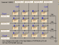
One method is to wrap all the keypad row-driving and column reading into a neat function that returns one value; new_key (the key which is pressed).
Then call that function as part of a loop, say every 1mS. Each time, if new_key==last_key then you increment a debounce count. If not, clear the debounce count.
Then after 20 good reads where new_key==last_key, you know the key was pressed for sure.
The same debounce count will work for "no key" too.


")