GPS NMEA antenna aiming tracker.

Thread Starter

camerart

Joined Feb 25, 2013
3,838
hi,
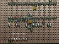
This image shows the connections as I saw it.

I will check your latest program.
[any chance you could use shorter file names, I only have a 22inch screen].:)

E

EDIT:
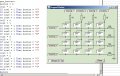
I have edited the button assignments to show your keypad changes.
Can you confirm that its the same as you have.?
Hi E,
Remember 8 digit max file names?

Here is the keypad layout and Button assignments, that are working, they should be the same as the program I posted last.

I also changed the TRISBs and the SYMBOLS.

C
 

Attachments

Thread Starter

camerart

Joined Feb 25, 2013
3,838
I don't understand the need for added resistors in this keypad circuit. I use keypads with PIC processors all the time, and I always set them up so the built-in pullups can do the job. But then I do have a tendency to fight to keep every additional component off the board!
Hi John,

I've seen various ways to connect keypads, I copied the Oshonsoft example, which has 4x1K and 4x10K resistors to GND.

C
 

ericgibbs

Joined Jan 29, 2010
21,458
Hi E,
Remember 8 digit max file names?

Here is the keypad layout and Button assignments, that are working, they should be the same as the program I posted last.

I also changed the TRISBs and the SYMBOLS.

C
hi C,
I had my rows starting at row1 at the top, it doesnt matter as long as its now working as you expected.
Whats the next step?
Eric
 

Thread Starter

camerart

Joined Feb 25, 2013
3,838
hi C,
I had my rows starting at row1 at the top, it doesnt matter as long as its now working as you expected.
Whats the next step?
Eric
Hi E,

Do you think it is key bounce that is causing the 'C' as I release any key on the keypad? I will change the letter keys to '$GGA', ',' 'N' 'E' etc.

I am trying to get the GPS to transmit to a receiver that I will connect to the RX pin on the PIC. I tried connecting the GPS directly to the pin, but it didn't work. I might need to add a MAX 232 to correct the voltage, I'll check. I'll let you know if I succeed in TX/RX.

C
 

ericgibbs

Joined Jan 29, 2010
21,458
Do you think it is key bounce that is causing the 'C' as I release any key on the keypad? I will change the letter keys to '$GGA', ',' 'N' 'E' etc.
1. Does the pressing the 'C' key display a 'C'.??
If not then:
2. Check that 'C' is not permanently ON/pressed, as this will cause a 'C' on every key release.

Use a Ohm meter
 

Thread Starter

camerart

Joined Feb 25, 2013
3,838
1. Does the pressing the 'C' key display a 'C'.??
If not then:
2. Check that 'C' is not permanently ON/pressed, as this will cause a 'C' on every key release.

Use a Ohm meter
At the PIC pins, the top row C,D,E,F all give 7MHz OFF and 1K ON on a meter. When I switch on a 'C' appears on the screen, and a 'C' appears after any key except 'C' is released. 'C' does not work. I'm sure your correct, but I haven't found the problem yet.

C
 

Art

Joined Sep 10, 2007
806
When you added the external resistors did you turn off the internal pullups?
I don't have any pic docs handy right now, but what makes you think a bit was going to be set to 1
just because you commented the instruction that resets to zero?

Rich (BB code):
'option_reg.7 = 0  'Enable Pull-Up's
What happens if you remove the line that checks for "C"?

Rich (BB code):
// a quick & dirty debounce
int debounce = 0;


if (debounce = 0) {
get_button();
if (button != 0) {
debounce = 150; // set debounce if button was pressed
} // button
} else {
if (debounce > 0) { // in case your complier decrements 0 to 0xFF
debounce--; // decrement debouce
}
}
 
Last edited:

ericgibbs

Joined Jan 29, 2010
21,458
hi Art.
The PU are set to OFF on power up, however as a 'make sure' I would include Intcon2./RBPU =1 in the program header. [the OP is using a 18F4520],

I think the
'option_reg.7 = 0 'Enable Pull-Up's is a left over from some other program.???

Eric
 

Attachments

Thread Starter

camerart

Joined Feb 25, 2013
3,838
hi Art.
The PU are set to OFF on power up, however as a 'make sure' I would include Intcon2./RBPU =1 in the program header. [the OP is using a 18F4520],

I think the
'option_reg.7 = 0 'Enable Pull-Up's is a left over from some other program.???

Eric
Hi E,

I deleted option_reg.7 =0 and added Intcon2./RBPU =1 it reported syntax error.

C
 

Thread Starter

camerart

Joined Feb 25, 2013
3,838
What happens if you remove the line that checks for "C"?
Hi Art,

I commented out 'If row1 = 1 Then button = "C".
When switched on:

The LCD is clear, all digits are correct, except 'C' which shows 'D'

Camerart.
 
Last edited:

ericgibbs

Joined Jan 29, 2010
21,458
hi C,
Check for a short circuit between pins 40 and 39 of you PCB track and keypad wiring, this would give the 'C' error character.

post a photo of the copper side of your PCB

E
 

Thread Starter

camerart

Joined Feb 25, 2013
3,838
Which version of the INTCON2 is up to you, some people prefer to use
Port Bit numbers as in INTCON2.7=1
and others prefer mnemonics as INTCON2.RBPU=1

I prefer the RBPU its easier for other people reading you program

E
Ok, Ill use RBPU thanks

C
 

Thread Starter

camerart

Joined Feb 25, 2013
3,838
hi C,
Check for a short circuit between pins 40 and 39 of you PCB track and keypad wiring, this would give the 'C' error character.

post a photo of the copper side of your PCB

E

Hi E,

As you see by the photo I've been checking for shorts etc, couldn't find any.

Checking between COL and ROWs all show 7Mhohm when button not pushed, and 1K when pushed.

C.
 

Attachments

ericgibbs

Joined Jan 29, 2010
21,458
hi C,
The Oshonsoft Basic keypad program is too primitive to use in a 'practical' circuit.
Switch bounce has not been considered, ie: no delay periods or validation of the sub routine output, etc.

You need to add delays and error checking to the subroutine if you plan to use the program in hardware.

E
 

Thread Starter

camerart

Joined Feb 25, 2013
3,838
hi C,
The Oshonsoft Basic keypad program is too primitive to use in a 'practical' circuit.
Switch bounce has not been considered, ie: no delay periods or validation of the sub routine output, etc.

You need to add delays and error checking to the subroutine if you plan to use the program in hardware.

E
Hi E,

Thanks for checking, I know the effort it took.

'Art' offered a de-bounce suggestion #187 (Thanks ART) if you're interested.

Here's an idea instead of a keyboard:
The location of the tracker needs to be entered (accurately), then Up, down, left and right, for scanning.

Add 4X buttons for Up, Down, Left, Right and a GPS plus receiver for NMEA data, on the Tracker.

The GPS and NMEA will each pass through channel 1 and 2 of a MAX 232, into a switch over switch. The signal goes into the UART RX on pin 26.

On initialisation: The GPS is read and shown on the LCD till it has settled down with a location, pressing one of the buttons enters the location into the Tracker location variable.

Then the 4x Buttons are programmed to be Up, down etc

The tracker is aimed at the NMEA source signal either by visual or previous information, once a signal is found, as seen on the LCD the buttons are released and the tracker takes over.

Camerart
 
Top