Facebook
 Google
 GitHub
 Linkedin
Hi,Hi,
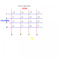
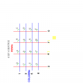
Look at this link for keypad matrix options.
https://www.google.co.uk/search?q=m...hannel=sb&gfe_rd=cr&ei=U8F8U4rPM4bR8geg74HICg
This is closest. double click the image.
http://www.mcuexamples.com/PIC-Matrix-Keypad-tutorial.php
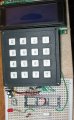
I don't think my keypad is like the ones you have pointed out, it's rather odd, as you can see from the attachment I posted. If you agree it's different, I have lots of mini push buttons, I could easily make a keypad on the circuit board. If we have a menu and use the 8 pins of PORTB (Push to GND) to choose 0-7 choices from the NMEA types GGA, RMC etc. Then by taking combinations of 0-7 to type the rest of the sentence.
C