hi C,
Located the source of the 20MHz LCD problem, when the READ_BUSY FLG is used the LCD_INIT should have been ignored by the compiler, instead it appears to have been using the default value of 100.
This basic sim demo works fast at 20MHz, I have also formatted the N and E values.
Give it a try.
E
Rich (BB code):
Define LCD_COMMANDUS = 100  'Command Delay (uS)
Define LCD_DATAUS = 50  'Data Delay (uS)
Define LCD_INITMS = 2

Define LCD_READ_BUSY_FLAG = 1  'NOTE: the above 3 defines are now ignored
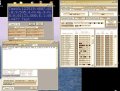
It didn't work, so I changed the clock frequency to 20MHz on the program, also the LCD connections as the TRISs on the program, still didn't work.
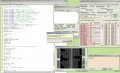
I have attached the latest program that you just sent me, with those changes. Also screen shot, showing the 'incorrect input' and the LCD data pins moving, but nothing on the screen.
Again it showed 'incorrect data' when pasting the $ sentence into USART.
I have attached the latest program that you just sent me, with those changes. Also screen shot, showing the 'incorrect input' and the LCD data pins moving, but nothing on the screen.
hi,
I have already explained the problem with LCD_INITMS in a previous post
Also you cannot use PORTC.6 for the UART and LCD, also explained.
Read my post #143.
If I correct your 30May0900.bas program as show in RED it works OK.
Rich (BB code):
Define LCD_DREG = PORTD  'Port for LCD Data
Define LCD_DBIT = 4  'Use upper 4 bits of Port
Define LCD_RSREG = PORTC  'Port for RegisterSelect (RS)
Define LCD_RSBIT = 3  '''6  'Port Pin for RS bit (pin25)
Define LCD_RWREG = PORTC
Define LCD_RWBIT = 5
Define LCD_EREG = PORTC  'Port for Enable (E)
Define LCD_EBIT = 4  'Port Pin for E bit (pin23)
Define LCD_BITS = 4  'Using 4-bit bus
Define LCD_LINES = 4  'Using 4 line Display
Define LCD_CHARS = 20
''Define LCD_COMMANDUS = 2000  'Command Delay (uS)
''Define LCD_DATAUS = 50  'Data Delay (uS)
Define LCD_INITMS = 2
Define LCD_READ_BUSY_FLAG = 1
Sorry missed the point! I changed RSBIT to 3 and now it shows 'TEST', but still doesn't accept $sentence. I even tried copying and pasting the $sentence from your last TXT. I'll check it all again.
Regarding the New circuit, we now have a 1 second flashing LED
Sorry missed the point! I changed RSBIT to 3 and now it shows 'TEST', but still doesn't accept $sentence. I even tried copying and pasting the $sentence from your last TXT. I'll check it all again.
My UART tool looks the same as yours to the letter. I tried HEX ticked and unticked. I can enter the $sentence, into the 'ENTER' box, but it doesn't appear in the 'Send string' box, only the error.
As you say Phew at last 20MHz XTL, Caps all over the place as you suggested, 22pF at the XTL, no resistors. (If you're asking about the MCLR pin, I changed it to RE3, so no resistor)
I'm sure all the TRIS values that I have at the beginning of my programs, is unprofessional, but it is a kind of commenting, that helps me remember what the pins are set to etc.
After the message you wrote between "" this arrived on the top screen.
If I type a character into 'send character' comes onto the top screen, if I send FF in the 'send byte' then a Y with accents appear on the top screen, if I enter a $sentence it reports 'incorrect input'
STOP the press!! I tried the latest program on a different computer and it all worked. I'll investigate tomorrow.
I've attached a keypad to the circuit, and TEST appears on the LCD and the LED is flashing 1/sec.
See attachment for the keypad pins, where you can see which pins are connected when each key is pressed. I'm a bit confused how to program the key inputs.
Now I have to get a received signal at the RX pin.
hi,
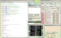
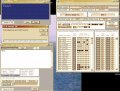
I have been looking at the maths using Oshonsoft, results are encouraging.
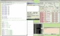
This is a clip of the output from the Sim UART and a lower section showing the results obtained from using Visual basic for the maths.
The results compare well considering that Oshonsoft is only 6 decimal digit resolution.
E
EDIT:
To avoid confusion the Azimuth Label should be Replaced by a Relative Bearing label.
Azimuth is normally a compass bearing value relative to North.
See attachment for the keypad pins, where you can see which pins are connected when each key is pressed. I'm a bit confused how to program the key inputs.
I'm not so quick at reading your maths homework, but it looks impressive. Am I correct in thinking that the Oshonsoft maths is 1/5 of a degree, different from the Visual basic. I also assume that a similar equation needs to be done for the Altitude angle?
Regarding the Keypad. On the attachment I posted, at the bottom of the TRISs, is a list, with the first key showing 'A 5+7' which means that when the A is pressed, then pins 5 and 7 would be connected. This is not the same as similar 4x4 keypads, as they show a straight forward matrix. Should I buy one of those before we go too far?
 Facebook
 Google
 GitHub
 Linkedin

")